Navigation:
Installation, Configuration and Operation of Hardware > Installation and Configuration of Additional Devices > Hanwell iSense >> Adding iSense Transmitters/Sensors to EMS
Adding iSense Transmitters/Sensors to EMS

Contents
The iSense Transmitter/Sensor must be added to EMS using the Family Type iSense.
•Follow this link for details on adding/assigning Sensors/Probes to a Zone.
Sensor Type Selection
The particular Sensor Type for your iSense Transmitter/Sensor must be defined in EMS from the Sensor Type drop-down menu:
•iSense Transmitter/Sensors should be added to the Hanwell software as the following Sensor Types:
iSense Transmitter/Sensor |
Add to Hanwell Software as Sensor Type: |
IS01-BN |
Thermistor R/H or Thermistor/RH/Digital. |
IS02-BN |
Thermistor/Thermistor/Digital. |
IS04 BR |
Absolute Atmospheric Pressure. |
IS04 BN |
Absolute Atmospheric Pressure. |
IS05-BN |
Digital variants: Thermistor/RH/Digital. |
IS06 BN |
Possible Sensor Types: |
IS07 BN |
Dual Linear |
IS08 BN |
Dual Linear or 3 Channel Linear |
IS09 BN |
Possible Sensor Types: |
| Note: | DO NOT attempt to configure the iSense Transmitter/Sensor with the legacy iSenseConfig Utility or iSense USB Configurator. |
| CAUTION: | Changing the Send Interval and Internal Logging Interval (Mins) values in EMS (Edit Mode) will flush any unsent data from the iSense Unit’s memory. |
iSense Virtual Pre-requisites
If this is the first iSense device you have purchased from Hanwell for use with your EMS/Synergy system, you must add your customer Global Unique Identifier (GUID) into EMS/Synergy before the iSense device can be used.
•You will have received an email from Hanwell Customer Operations or your Distributor, with your Customer GUID
•Please follow the instructions in the email, outlined below, to enter the GUID into your EMS/Synergy system.
1.Run the EMS Config Utility:
▪All Programs > Hanwell Instruments > EMSConfig
2.Click Yes and Ok when requested, by the displayed dialogs, until the main EMS Configuration Ver.X.X.X.X window is shown. See Figure 217 below:
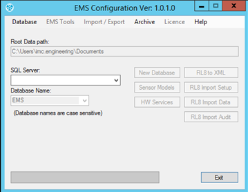
Figure 217
3.If the SQL Server: drop down list is populated:
Select the required SQL Server from the list.
If the SQL Server: drop down is not populated:
i.Select Database > Manual Connection. See Figure 218 below:
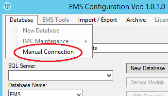
Figure 218
ii.Enter the required database details into the displayed Manual Connection dialog box. See Figure 219 below:
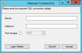
Figure 219
iii.Click Login Details.
iv.Either:
Select Windows Account.
Or:
Enter the login details for your SQL Server Administrator.
If you do not know these details, contact your System Administrator or IT Service provider, please DO NOT contact Hanwell Support as we do not know your SQL account details.
4.Click Accept on the displayed dialogs until you return to the main EMS Configuration Ver. X.X.X.X window.
5.Select EMS Tools from the Windows main menu bar.
6.Select GPRS GUID. See Figure 220 below:
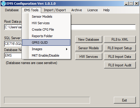
Figure 220
7.Copy and paste the provided GUID, sent in the email from Hanwell Customer Operations or your Distributor, into the GPRS GUID dialog box. See Figure 221 below:
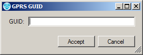
Figure 221
8.Click Accept.
Transmitter/Sensor Unit Operation
The iSense Units will log data on-board at the pre-set Log Interval and, in due course, send the logged data to the Hanwell Remote Data Service.
This Send process will occur under the following circumstances:
•After the SendInterval
Or
•If the measurement is in alarm and the Send interval is less than 2 hours. Otherwise, the Unit will transmit at the normal transmit interval.
In the event of a communications failure, the device will buffer up to 400k readings and gradually transmit this after communications are restored (assuming that the Unit’s batteries have enough capacity to transmit the logged data), in reverse time order, sending its current data packet, plus the most recent three packets which weren’t successfully transmitted.
If the measurement goes into alarm, the Unit will start to transmit at every Measurement Interval for a period of up to 2 hours, if the Send interval is not set to be greater than 2 hours. After this time, it will revert to its programmed behaviour.
•The alarm will not be reset until levels have returned to normal for three logs.
The device sends its battery voltage with each message; this can be viewed via EMS.
Alarm Handling
It is possible to set High and Low Level Alarms on each individual iSense channel.
•These iSense Level Alarms equate to High High and Low Low Level Alarms in EMS and High and Low Level alarms in Synergy and Notion Pro respectively.
| Note: | It is important to remember that, as the device only calls in, these values can only be changed on a standard connect cycle. This cycle will happen sometime later – possibly many hours later – after the EMS change. |
Prior to an alarm, the sensors/probes are sampled at the Nominal Logging Interval and data transmitted periodically however, if an alarm condition is detected, it will transmit this at the following Measurement Interval if the send interval is less than 2 hours.
Assuming the GSM network is up and running perfectly, there will be up to a further 8 minutes before it appears on screens because of Re-director and EMS delays.
| Note: | Any provider network delays are outside of our control and may be added to this time. |
The device will continue to send data rapidly for 2 hours (at every Measurement Interval) after the initial transition and then revert to Normal Mode.
To cope with the system delays you should set the Alarm Reactivation Time on the PC to a minimum of 30 minutes. Do not manually reset it prior to this or you risk seeing the same alarm reported twice.