Navigation:
Installation, Configuration and Operation of Hardware > Installation and Configuration of Control Devices >> CR3 NW (Network) - Configuration
CR3 NW (Network) - Configuration

Contents
Configuration of CR3 NW(s) is normally done on the network, but in some instances, it may be necessary to connect to the CR3 NW(s) directly.
•Before the CR3 NW(s) can be configured, fixed IP addresses should be assigned to each Unit by the Network Manager.
•You should also know the Subnet and Gateway addresses.
•The CR3 NW should be connected to the network using a straight-through network lead (supplied).
Assigning IP Addresses to CR3 NW(s)
1.Access the Network Configuration Utility via the EMS Remote Management Tool:
i.Run the EMS Remote Management Tool. See the EMS Remote Management Tool Manual (Document Number: IM6000).
•The EMS Remote Management Tool window is displayed. See Figure 138 below:
Figure 138
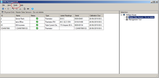
ii.Select Tools from the main toolbar (see Figure 138 above) and then click on SR2 Network Configuration in the displayed menu.
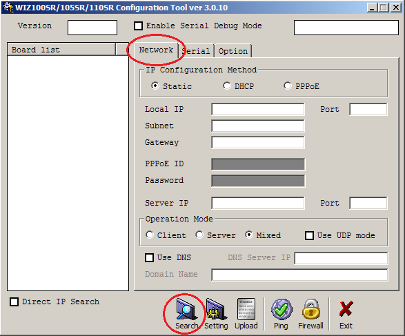
•The Network Configuration Utility's home page is displayed, with the Network tab selected. See Figure 139 below:
Figure 139
2.Enter Details into the Network Configuration Utility's Window
i.Click the Search icon on the Configuration Tool toolbar. See Figure 139 above.
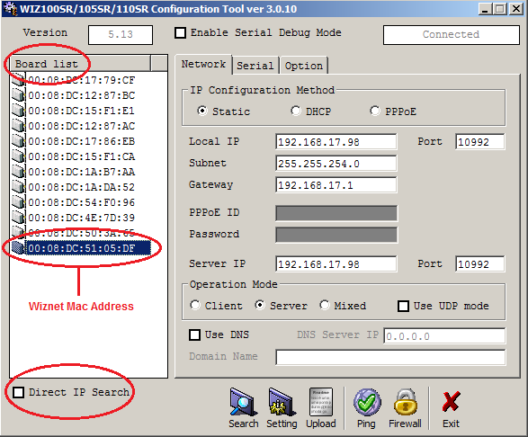
•The program will search for any CR3 NWs and populate the Board list field on the left of the window with a list of all of the CR3 NWs on the network. See Figure 140 below:
Figure 140
•The Complete searching window will be displayed when all CR3 NWs have been located.
Click on Close to dismiss the window. See Figure 141 below:
Figure 141
•If there are no CR3 NWs found, you will need to get the IT Department to check the Network.
•The CR3 NWs can be connected directly to a laptop using a crossover cable to confirm their operation.
| Note: | You must be on the same subnet for this broadcast to work. If not, tick the Direct IP Search box (See Figure 140 above). |
ii.Click once on the Wiznet Mac address of the required CR3 NW Unit in the Board List field to select it (See Figure 140 above).
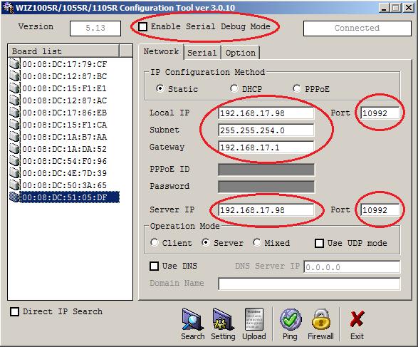
iii.Enter the Network Configuration details into the Network field as specified by your Network Manager and/or as found in the EMS IT Pre-Requisites document (Document Number: GD6101) i.e.:
•Local IP
Local IP must be as given to you by IT.
•Subnet
Subnet must be as given to you by IT.
•Gateway
Gateway must be as given to you by IT.
•Server IP
Server IP should be set to match the Local IP Address
•Port
The Port numbers must both be the same and as given to you by IT and/or as found in the EMS IT Pre-Requisites Document (Document Number: GD6101). Hanwell recommended Default Port Number 10992. See Figure 142 below:
Figure 142
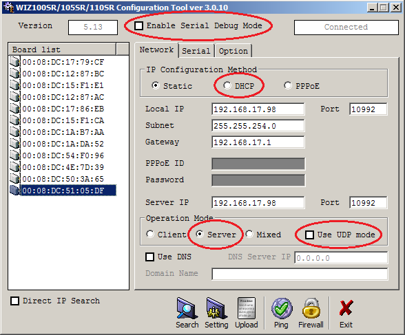
iv.On the Network tab:
a)Set Operation Mode to Server.
b)Confirm that the following options ARE NOT TICKED/CHECKED in the Network Configuration Utility's window:
•Enable Serial Debug Mode
•Enable DHCP Mode
•Use UDP Mode
| Warning: | Selecting any of these options and then clicking on the Settings icon WILL disable the Control Device and require its return to the Manufacturer for resetting. |
See Figure 143 below:
Figure 143
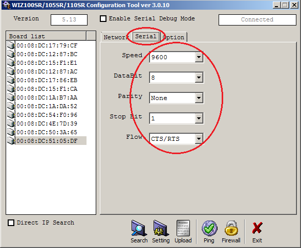
v.Click on the Serial tab.
vi.Select the following values from the highlighted fields' drop-down lists on the Serial tab:
Smart Receiver Setting |
|
Speed |
115200 |
Parity |
None |
Data Bit |
8 |
Stop Bit |
1 |
Flow Ctrl |
CTS / RTS |
See Figure 144 below:
Figure 144
vii.Enter the following values into the highlighted fields on the Option tab.
Smart Receiver Setting |
|
Inactivity Time |
10 |
Time |
5 |
Size |
255 |
Char |
00 |
See Figure 145:
Figure 145
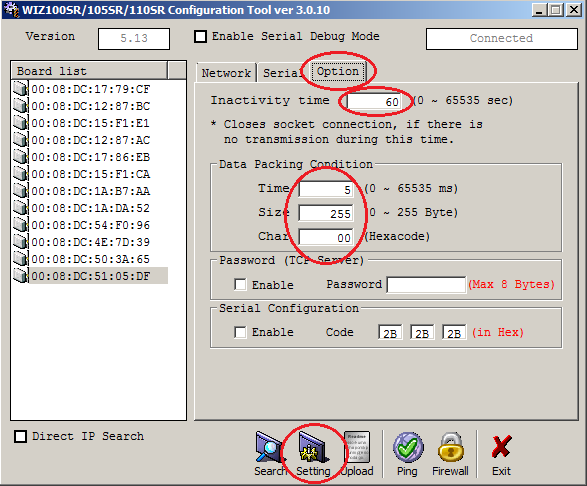
viii.Once all the changes have been made, click on the Setting icon to save the configuration settings. See Figure 145 above.
•The following Status windows are displayed:
ix.Click on Close on the Complete setting window.
x.Repeat Steps ii to viii for any additional CR3 NWs on the Network.