
Contents
This feature lets you set Filter Limits for the selected Sensor/Transmitter.
| Example 1: | If, say, a Sensor/Transmitter is located in or near to an electrical switch panel, which can be very noisy electrically, occasional interference may occur on the radio link, which would be seen on the graph as a large spike in the data. Sensor Filters are designed to remove such interference. |
| Caution: | Filters should only be used in exceptional circumstances. |
Accessing and Editing the Sensor Filters
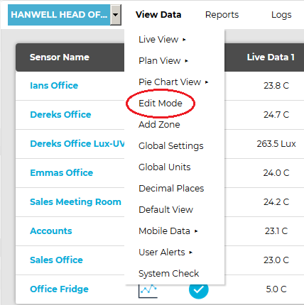
1.From the required Site's Live View window, select Edit Mode from the main View Data menu. See Figure 1009 below: Figure 1009
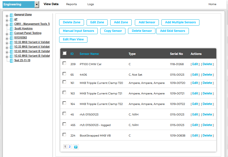
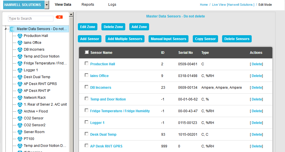
•The Editing and Configuration window is displayed. See Figure 1010 below: Figure 1010
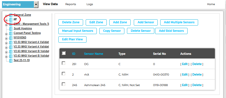
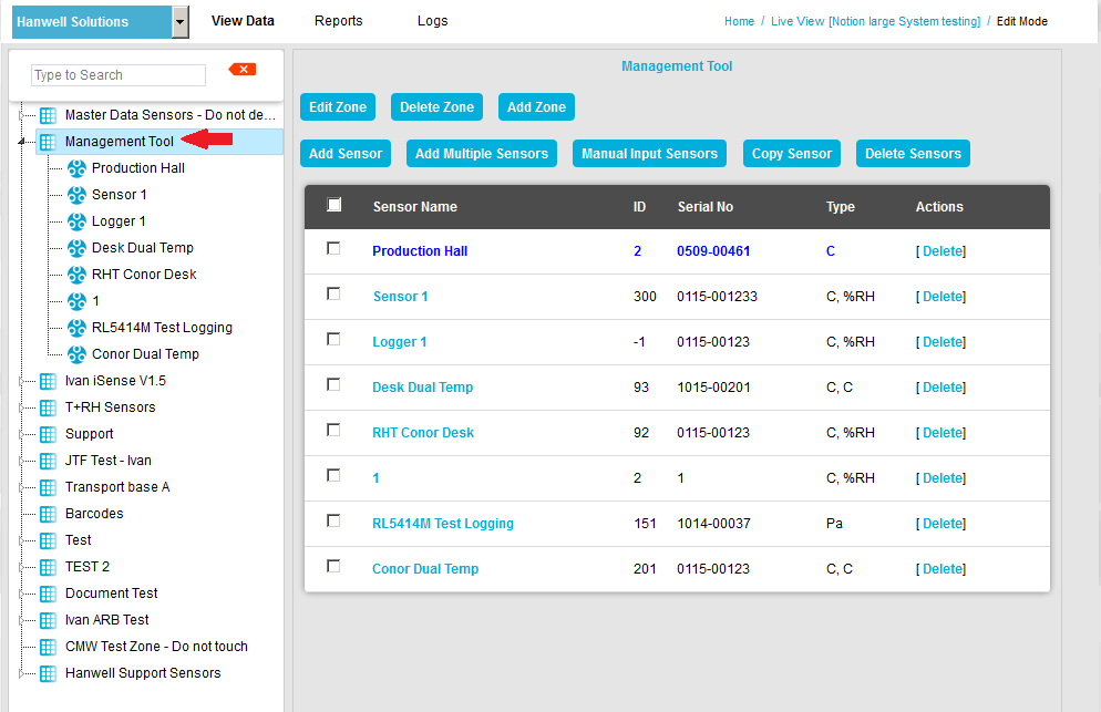
•By default, the Sensor and Zone editing/configuration window for the Zone at the top of the left-hand menu is displayed. •To display another Zone's Editing and Configuration window, click on the entry for the required Zone in the left-hand menu. For an example, see Figure 1011 below: Figure 1011
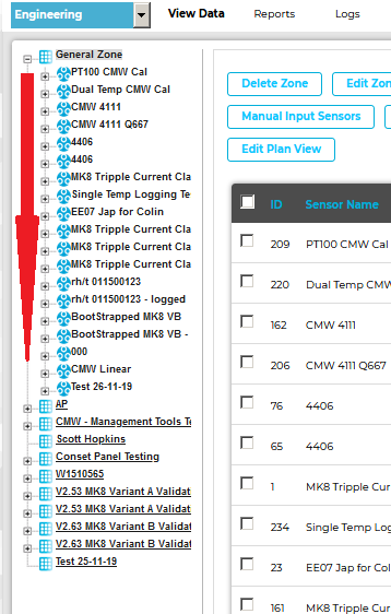
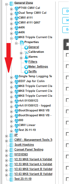
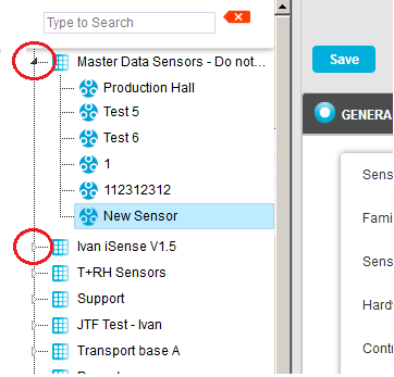
2.In the left-hand menu of the displayed Editing and Configuration window, click on the + symbol next to the Zone containing the Current Clamp Sensors to be edited. •The selected branch will expand showing all of the available sensors for the selected Zone. See Figure 1012 below: Figure 1012
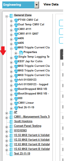
3.Click on the + symbol next to the Sensor name to view the properties of the Sensor that is to be Edited. •This will expand the branch again to show the Properties folder for the Sensor. See Figure 1013 below: Figure 1013
4.Click on the + symbol next to Properties to access the individual Sensor properties. •This will expand the branch again to show the Sensor's configurable Properties. See Figure 1014 below: Figure 1014
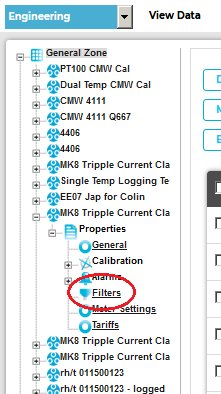
5.Click on the Filters icon. See Figure 1015 below: Figure 1015
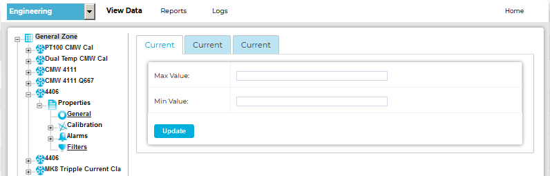
•The Sensor's Filter window is displayed. ➢Tabs are displayed for each of the selected Sensor's channels (a Triple Current Clamp Sensor in this example). See Figure 1016 below: Figure 1016
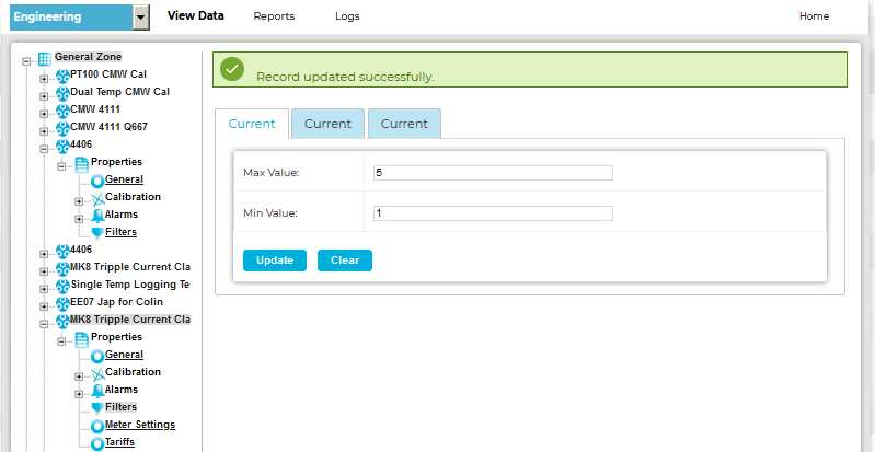
6.To activate each channel's Filters, enter the required Minimum and Maximum values into the Min Value: and Max Value: dialog boxes. Note: For Temperature Channel Filters, the values should be whole numbers within the range 50 for the Maximum value and -40 for the Minimum value. 7.Click on Update. See Figure 1016 above. •This will save the Filter values for the selected Channel of the currently selected Sensor/Transmitter. •The following message will be displayed in the Sensor's Filter window. See 1017 below:
•For dual or triple Channel Sensor/Transmitters, repeat the above process for the other channels if required.
|
1.From the required Site's Live View window, select Edit Mode from the main View Data menu. See Figure 1017 below:
Figure 1017
•The Edit Mode window is displayed. See Figure 1018 below:
Figure 1018
•By default, the Sensor and Zone editing/configuration window for the Zone at the top of the left-hand menu is displayed.
•To display another Zone's Edit Mode window, click on the entry for the required Zone in the left-hand menu. For an example, see Figure 1019 below:
Figure 1019
2.Either:
i.In the left-hand list of the Zone's Edit Mode window, click on the small 'arrow' symbol to display a list of the Sensors associated with the Zone. See Figure 1020 below:
Figure 1020
ii.In the left-hand list, click on the required Sensor's icon ![]() .
.
Or:
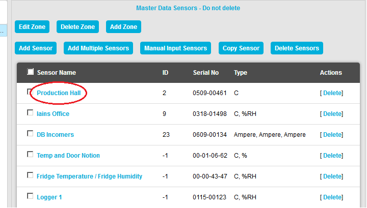
In table in the Zone's Edit Mode window, click on the required Sensor's name in the Sensor Name column. See Figure 1021 below:
Figure 1021
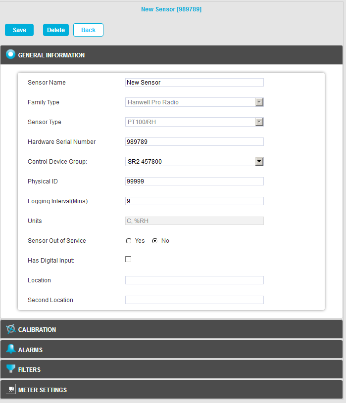
•The Edit Mode window for the selected Sensor is displayed. See Figure 1022 below:
Figure 1022
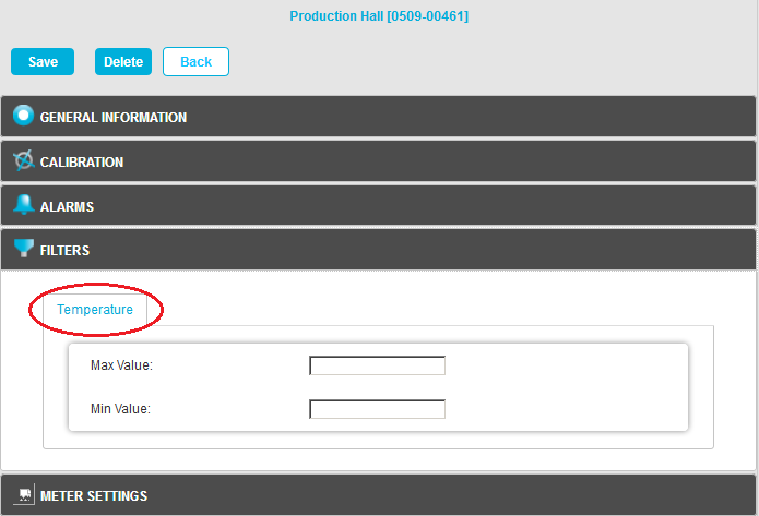
3.Click on FILTERS to display the Filters pane for the selected Sensor/Transmitter.
•Tabs are displayed for each of the selected Sensor's channels. See Figure 1023 below:
Figure 1023
|
|
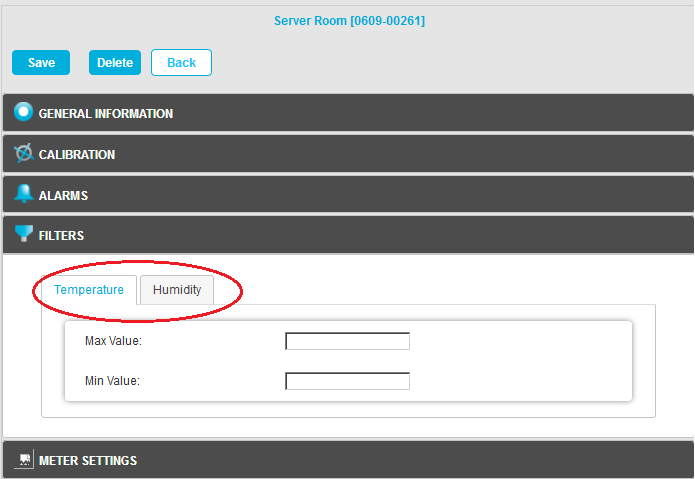
4.To activate each channel's Filters, enter the required Minimum and Maximum values into the Min Value: and Max Value: dialog boxes.
•For Temperature Filters, the values should be whole numbers within the range 50 for the Maximum value and -40 for the Minimum value.
5.Click on Save. See Figure 1023 above.
•This will save the Filter values for the currently selected Sensor/Transmitter.
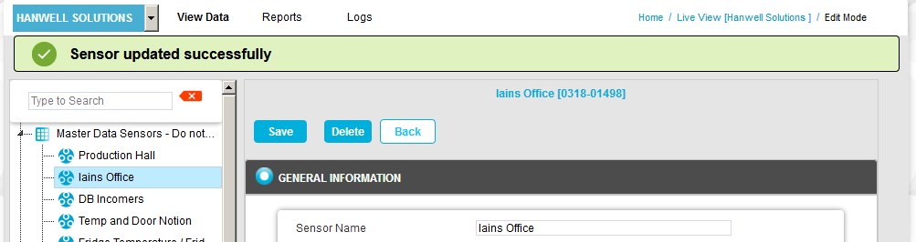
•The following message will be displayed and you will be returned to the GENERAL INFORMATION pane. See 1024 below:
Figure 1024
•For dual or triple Channel Sensor/Transmitters, repeat the above process for the other channels.
| Caution: | Setting Filters will cause data to be rejected above and below the Filter's limits. Check that any Filter limits set are above and below the expected ranges. |