Navigation:
Installation, Configuration and Operation of Hardware > Installation and Configuration of Control Devices > Installing the SR2 Receiver >> SR2 Advanced Hardware Configuration
SR2 Advanced Hardware Configuration

Contents
The SR2 is sent out set to its default Hardware configuration.
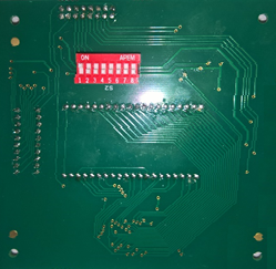
The following Hardware settings can be changed, via a set of 8 DIP switches on the back of the display PCB, accessed by opening the Unit's front cover (see Figure 168 below):
| Note: | Switches 5 - 8 inclusive are not used and should be set to OFF. |
Figure 168