Navigation:
System Configuration Sensors > Configuring Sensors > Alarms >> Alarm Parameters/Levels
Alarm Parameters/Levels

Contents
Editing the Alarm Parameters/Levels
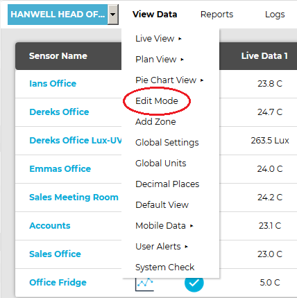
1.From the required Site's Live View window, select Edit Mode from the main View Data menu. See Figure 871 below:
Figure 871
2.In the left-hand menu of the displayed Editing and Configuration window, click on the + symbol next to the Zone containing the Sensors to be accessed. •The selected branch will expand showing all of the available sensors for the selected Zone. See Figure 872 below: Figure 872
3.Click on the + symbol next to the Sensor name to view the properties of the Sensor that is to be Edited. •This will expand the branch again to show the Properties folder for the Sensor. See Figure 873 below: Figure 873
4.Click on the + symbol next to Properties to access the individual Sensor properties. •This will expand the branch again to show the Sensor's configurable Properties. See Figure 874 below: Figure 874
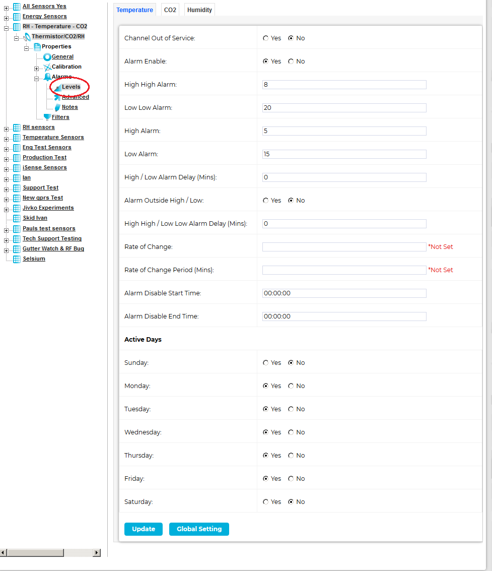
5.Click on the + sign next to the Alarms icon to expand the Alarm property entries for the selected Sensor. 6.Click on the Levels icon to display the Alarm Settings window for the selected Sensor/Transmitter. See Figure 875 below: Figure 875
•The Sensor/Transmitter in this example is a three channel Temperature, Humidity and CO2 device. You will see three tabs at the top of the window one marked Temperature and highlighted (in white) the other two marked CO2 and Humidity. ➢The highlighted tab is the active tab. ➢The tab names will change depending on sensor type. ➢The number of tabs will change depending on the number of channels. 7.Enter or Edit the required Alarm Levels/Parameters; details of these are outlined below: •Channel Out of Service This feature allows a single channel on a multiple channel device to be taken out of service. This is useful as it may not be desirable to take the whole Sensor/Transmitter out of service. For example, if a dual channel temperature transmitter was being used to measure the temperatures in a fridge-freezer and the freezer had failed or was not in use, just the channel associated with the freezer could be taken out of service. This would allow alarms from the fridge to come through the System, but there would be no alarms from the unused freezer. To take a channel out of service, select the appropriate channel's tab and tick the check box. •When the channel is required again untick the check box. •Alarm Enable If a Sensor/Transmitter is temporally out of service, or if the alarms are temporally not required, rather than set all the alarm settings to zero, the alarms can be disabled. ➢To disable the alarms untick the check box. When the alarms are required again, tick the check box. •High High Alarm The High High Alarm is the highest level alarm that can be set on the System; this alarm should be set at a level that warns the User of potential damage. To set the High High Alarm, type a value in the dialog box next to High High Alarm. The level can be set to one decimal place and should be entered in the format: - 25 for a whole number or - 25.5 for a fraction. •High Alarm The High Alarm would be set to a level that would represent the highest point of the desirable working range. To set the High Alarm, type a value in the dialog box next to High Alarm. The level can be set to one decimal place and should be entered in the format: 25 for a whole number or 25.5 for a fraction. •Low Alarm The Low Alarm would be set to a level that would represent the lowest point of the desirable working range. To set the Low Alarm type a value in the dialog box next to Low Alarm. The level can be set to one decimal place and should be entered in the format: 25 for a whole number or 25.5 for a fraction. •Low Low Alarm The Low Low Alarm is the lowest level alarm that can be set on the System; this alarm should be set at a level that warns the User of potential damage. To set the Low Low Alarm, type a value in the dialog box next to Low Low Alarm. The level can be set to one decimal place and should be entered in the format: - 5 for a whole number or - 5.5 for a fraction. •High/Low Alarm Delay (Mins) A delay in minutes can be set for the High/Low Alarms to prevent false or unnecessary alarms. ➢Be aware of Alarm Fatigue Syndrome.
If High/Low Alarms are set: ➢Without a High/Low Alarm Delay, an alarm would be generated every time the door is opened. ➢With a High/Low Alarm Delay of 15 minutes set for the High/Low Alarms, there would be no alarm generated when the door was initially opened; however, if the door was left open for more than 15 minutes, then an alarm would be generated. To enter a High/Low Alarm Delay, enter the time in minutes in the dialog box next to High/Low Alarm Delay (Mins) in the format: 15 •Alarm Outside High/Low To activate High/Low Alarm Delays tick the check box. To disable High/Low Alarm Delays untick the check box. •High High/Low Low Alarm Delay (Mins) This feature allows a delay to be activated on the High High and Low Low alarms. ➢It is generally accepted that no delay is enabled on the High High and Low Low level alarms as these are normally the fail safe alarm levels. If delays are used here, it may be for circumstances such as a very small delay being used to avoid a single out of specification reading generating alarms. To put a delay on the High High and Low Low level alarms, type a value (in minutes) in the dialog box next to High High/Low Low Alarm Delay (Mins) in the format: 5 •Rate of Change This feature activates Rate of Change alarms. ➢Depending on the Sensor/Transmitter's application, a High and Low level alarm may not be appropriate. ➢A Rate of Change alarm is a mechanism that monitors how fast a parameter is changing and generates an alarm based on the selected criteria. ➢The Rate of Change parameter defines the amount of Units changing over the Rate of Change Period (see below). To set the Rate of Change enter a value in the Rate of Change: dialog box corresponding to the measurement Units for that channel. ➢For a Temperature channel, the Units would be degrees centigrade and the value would be entered in the format: 10 in this case, for a Temperature change of 10°C. •Rate of Change Period (Mins) This feature is used in conjunction with the Rate of Change value above and defines the time period associated with the Rate of Change value. This value is defined in minutes and is entered into the Rate of Change Period (Mins) dialog box in the format: 5
•Alarm Disable Start Time In conjunction with the Alarm Disable End Time function (see below), this feature allows alarms to be disabled during certain time periods. For example: If a room is used during the day to work on sensitive items, alarms would be required during the day, but not required during the night. To set the Alarm Disable Start Time, enter the required delay into the Alarm Disable Start Time: dialog box in the format: 18:00:00 in hours, (24 hour clock format), minutes and seconds. In this example, all alarms would be disabled after 18:00. •Alarm Disable End Time This feature works together with Alarm Disable Start Time and defines the reactivation time for alarms following their disabling. To set the Alarm Disable End Time, enter the time in the Alarm Disable End Time dialog box in the format: 08:00 in hours, (24 hour clock format), minutes and seconds. In this example, all alarms for this device will be activated again after 08:00:00. Active Days This functionality is used to define which on which days Alarms are active or not. •It is used in conjunction with the Alarm Disable Start Time and Alarm Disable End Time functions outlined above to precisely define the periods when Alarms are active/inactive. •Tick the relevant boxes to define the days when Alarms are to be ACTIVE. For example: Where sensitive goods are worked on during the week and put away each evening and at the weekend alarms would not be required at these times. 8.Once you are happy with your selections, click on the Save button. •If the Update has been successful, you will be returned to the Zone's Edit Mode window and the following message will be displayed. See 876 below: Figure 876
•The above sequence can be repeated for the second and third channels if necessary. |


•The Site's Edit Mode window is displayed. See Figure 877 below:
Figure 877
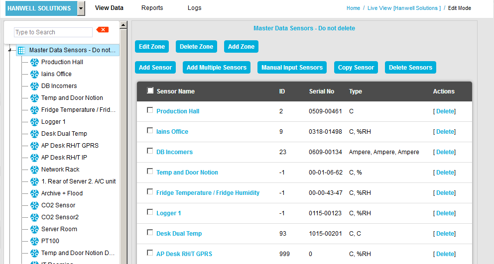
•By default, the Sensor and Zone editing/configuration window for the Zone at the top of the left-hand menu is displayed.
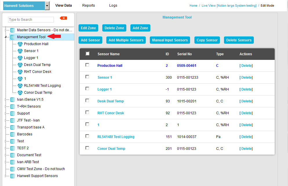
•To display another Zone's Edit Mode window, click on the entry for the required Zone in the left-hand menu. For an example, see Figure 878 below:
Figure 878
2.Either:
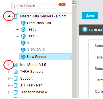
i.In the left-hand list of the Zone's Edit Mode window, click on the small 'arrow' symbol to display a list of the Sensors associated with the Zone. See Figure 879 below:
Figure 879
ii.In the left-hand list, click on the required Sensor's icon ![]() .
.
Or:
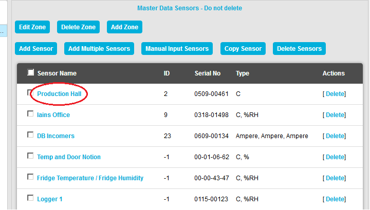
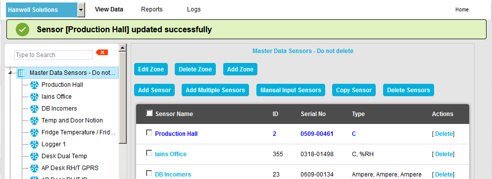
In table in the Zone's Edit Mode window, click on the required Sensor's name in the Sensor Name column. See Figure 880 below:
Figure 880
•The Edit Mode window for the selected Sensor is displayed. See Figure 881 below:
Figure 881
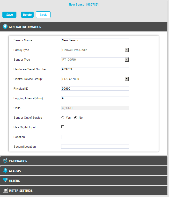
3.Click on the Alarms pane at the bottom of the Edit Mode window to access the Alarm Parameter/Level functionality. See Figure 881 above.
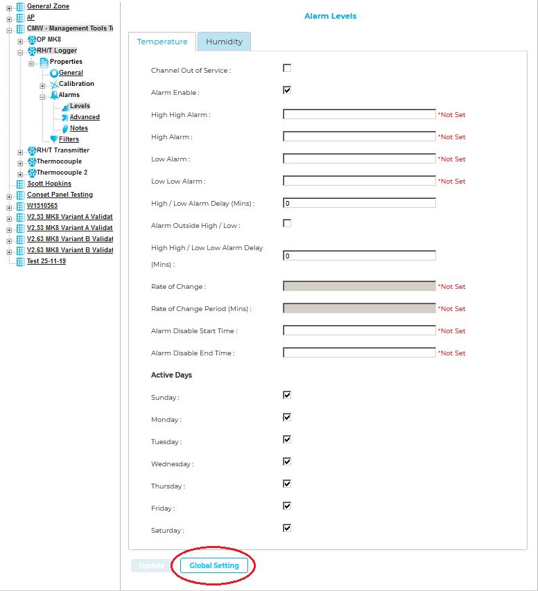
•The ALARMS pane is displayed. See Figure 882 below:
Figure 882
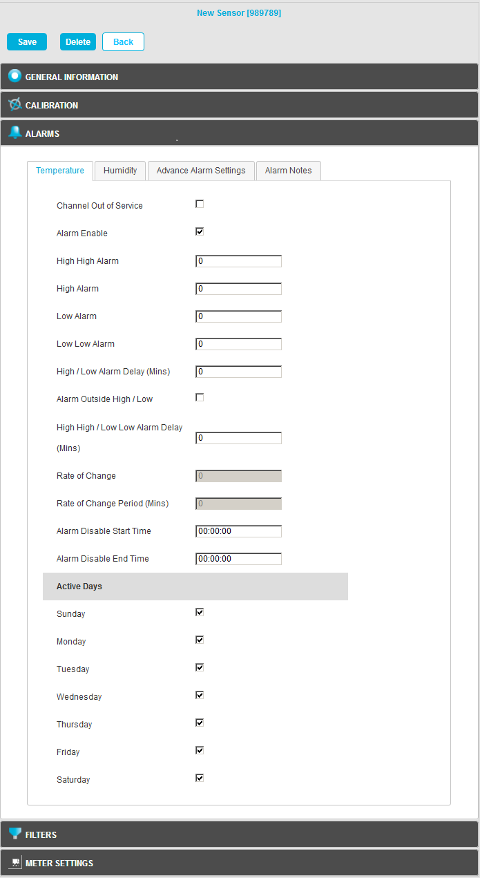
•The Sensor/Transmitter in this example is a two channel Temperature and Humidity device.
You will see their two tabs at the top of the window, one labelled Temperature and highlighted (in blue) and the other labelled Humidity.
➢The highlighted tab is the active tab.
➢The tab names will change depending on Sensor type.
➢The number of tabs will change depending on the number of channels.
4.Enter or Edit the required Alarm Levels/Parameters; details of these are outlined below:
•Channel Out of Service
This feature allows a single channel on a multiple channel device to be taken out of service.
This is useful as it may not be desirable to take the whole Sensor/Transmitter out of service . For example, if a dual channel temperature transmitter was being used to measure the temperatures in a fridge-freezer and the freezer had failed or was not in use, just the channel associated with the freezer could be taken out of service. This would allow alarms from the fridge to come through the System, but there would be no alarms from the unused freezer.
To take a channel out of service, select the appropriate channel's tab and tick the check box.
➢When the channel is required again untick the check box.
•Alarm Enable
If a Sensor/Transmitter is temporally out of service, or if the alarms are temporally not required, rather than set all the alarm settings to zero, the alarms can be disabled.
➢To disable the alarms untick the check box. When the alarms are required again, tick the check box.
The High High Alarm is the highest level alarm that can be set on the System; this alarm should be set at a level that warns the User of potential damage.
To set the High High Alarm, type a value in the dialog box next to High High Alarm.
The level can be set to one decimal place and should be entered in the format: - 25 for a whole number or - 25.5 for a fraction.
The High Alarm would be set to a level that would represent the highest point of the desirable working range.
To set the High Alarm, type a value in the dialog box next to High Alarm.
The level can be set to one decimal place and should be entered in the format: 25 for a whole number or 25.5 for a fraction.
The Low Alarm would be set to a level that would represent the lowest point of the desirable working range.
To set the Low Alarm, type a value in the dialog box next to Low Alarm.
The level can be set to one decimal place. The level can be set to one decimal place and should be entered in the format: 25 for a whole number or 25.5 for a fraction.
The Low Low Alarm is the lowest level alarm that can be set on the System; this alarm should be set at a level that warns the User of potential damage.
To set the Low Low Alarm, type a value in the dialog box next to Low Low Alarm.
The level can be set to one decimal place and should be entered in the format: - 5 for a whole number or - 5.5 for a fraction.
•High/Low Alarm Delay (Mins)
A delay in minutes can be set for the High/Low Alarms to prevent false or unnecessary alarms.
➢Be aware of Alarm Fatigue Syndrome.
| For example: | In many buildings rooms are air conditioned to keep the environmental conditions constant, the conditions in any room change when doors are opened but soon recover when the door is closed again. In such circumstances, when a door is opened, the temperature may drop but recover back to normal 10 minutes after the door is closed. |
If High/Low Alarms are set:
➢Without a High/Low Alarm Delay, an alarm would be generated every time the door is opened.
➢With a High/Low Alarm Delay of 15 minutes set for the High/Low Alarms, there would be no alarm generated when the door was initially opened; however, if the door was left open for more than 15 minutes, then an alarm would be generated.
To enter a High/Low Alarm Delay, enter the time in minutes in the dialog box next to High/Low Alarm Delay (Mins) in the format: 15
•Alarm Outside High/Low
To activate High/Low Alarm Delays tick the check box.
To disable High/Low Alarm Delays untick the check box.
•High High/Low Low Alarm Delay (Mins)
This feature allows a delay to be activated on the High High and Low Low alarms.
➢It is generally accepted that no delay is enabled on the High High and Low Low level alarms as these are normally the fail safe alarm levels. If delays are used here, it may be for circumstances such as a very small delay being used to avoid a single out of specification reading generating alarms.
To put a delay on the High High and Low Low level alarms, type a value (in minutes) in the dialog box next to High High/Low Low Alarm Delay (Mins) in the format: 5
•Rate of Change
This feature activates Rate of Change alarms.
➢Depending on the Sensor/Transmitter's application, a High and Low level alarm may not be appropriate.
➢A Rate of Change alarm is a mechanism that monitors how fast a parameter is changing and generates an alarm based on the selected criteria.
➢The Rate of Change parameter defines the amount of Units changing over the Rate of Change Period (see below).
To set the Rate of Change enter a value in the Rate of Change: dialog box corresponding to the measurement Units for that channel.
➢For a Temperature channel, the Units would be degrees centigrade and the value would be entered in the format: 10 in this case, for a Temperature change of 10°C.
•Rate of Change Period (Mins)
This feature is used in conjunction with the Rate of Change value above and defines the time period associated with the Rate of Change value.
This value is defined in minutes and is entered into the Rate of Change Period (Mins) dialog box in the format: 5
| For example: | In conjunction with the Rate of Change value above, entering a value of 5 in the Rate of Change Period (Mins) dialog box would generate an alarm if the temperature changed by more than 10°C in 5 minutes. |
•Alarm Disable Start Time
In conjunction with the Alarm Disable End Time function (see below), this feature allows alarms to be disabled during certain time periods.
For example:
If a room is used during the day to work on sensitive items, alarms would be required during the day, but not required during the night.
To set the Alarm Disable Start Time, enter the required delay into the Alarm Disable Start Time: dialog box in the format: 18:00:00 in hours, (24 hour clock format), minutes and seconds. In this example, all alarms would be disabled after 18:00.
•Alarm Disable End Time
This feature works together with Alarm Disable Start Time and defines the reactivation time for alarms following their disabling.
To set the Alarm Disable End Time, enter the time in the Alarm Disable End Time dialog box in the format: 08:00 in hours, (24 hour clock format), minutes and seconds. In this example, all alarms for this device will be activated again after 08:00:00.
Active Days
This functionality is used to define which on which days Alarms are active or not.
•It is used in conjunction with the Alarm Disable Start Time and Alarm Disable End Time functions outlined above to precisely define the periods when Alarms are active/inactive.
•Tick the relevant boxes to define the days when Alarms are to be ACTIVE.
For example:
Where sensitive goods are worked on during the week and put away each evening and at the weekend alarms would not be required at these times.
5.Once you are happy with your selections, click on the Save button.
•If the Update has been successful, you will be returned to the Zone's Edit Mode window and the following message will be displayed. See 883 below:
Figure 883
• The above sequence can be repeated for the second and further channels if necessary.
Digital Alarms are generated by digital channels that record data from devices such as Flood Sensors and Door Open/Closed Sensors.
•Digital channels can only have two states, which are analogous to Open or Closed. Figure 884 below shows the Alarm Levels settings view for a Digital channel:
Figure 884
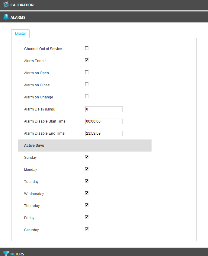
| Note: | The Alarms Settings window for earlier versions of EMS may be slightly different, as shown here. |
|
•The binary state of the digital channel is logged at the chosen Logging Interval.
Digital Alarms - Door Open/Closed Sensors
Door Open/Closed Sensors are a particular type of Digital Sensor which monitors the binary state of the digital channel, but also immediately transmits the binary state following a change and logs that change in the Alarm Log, if Alarms are set up.
| Note: | As a consequence of this, it is possible for an Alarm to be triggered by a Door Sensor between logging points, which will appear in the Alarm Log, but not log as a data point in the Hardware. |
The following Alarms can be selected for Door Sensors:
•Alarm on Open would give an alarm if someone opened the door.
•Alarm on Close would give an alarm if someone closed the door.
•Alarm on Change would give an alarm if someone opened or closed the door.
If there are many Sensors/Transmitters on the same System, doing the same function in different spaces, it can be tedious and error-prone to go through all of the Sensors/Transmitters on the System and set Alarm Levels for each Sensor/Transmitter individually.
•In such circumstances, the Global Settings function can apply the currently selected Sensor/Transmitter's Alarm Level settings to other Sensor/Transmitters.
Applying Settings Globally
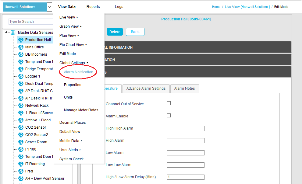
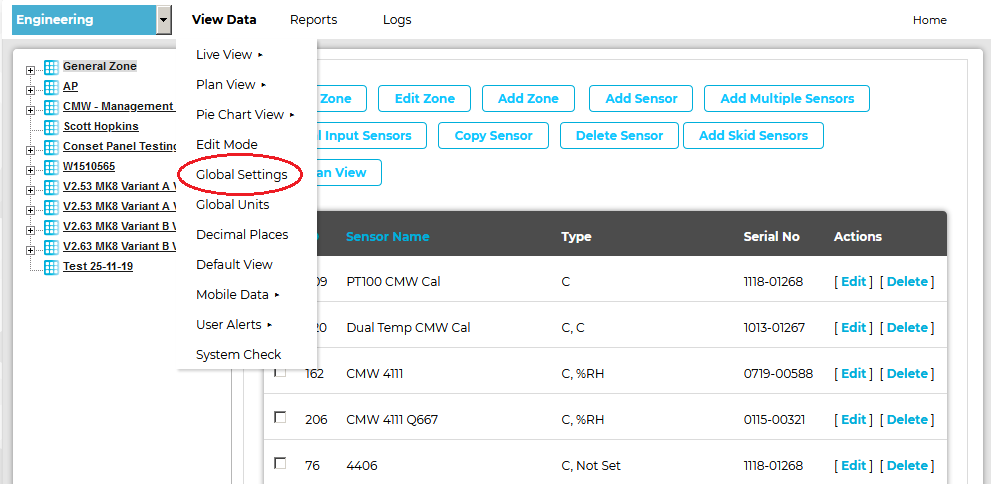
1.With the Alarms pane selected, click on Global Settings in View Data drop-down menu.
2.From the displayed sub-menu, select Alarm Notification. See 885 below:
Figure 885
| Note: | For earlier versions of EMS, click on the Global Settings entry in the View Data drop down menu. See here. |
|
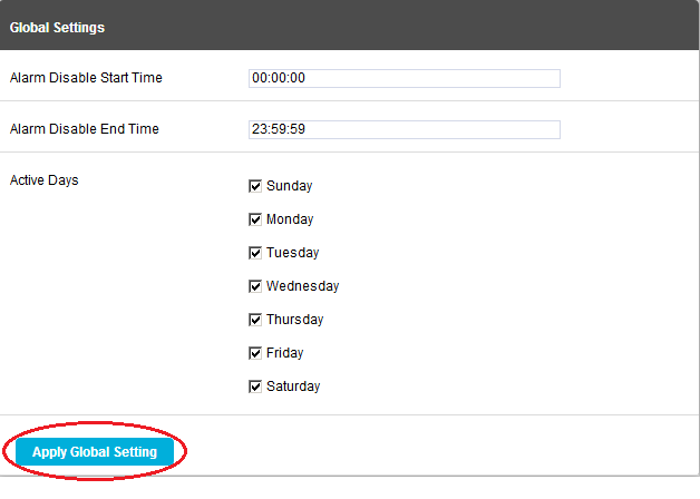
•The Global Settings window is displayed. See Figure 886 below:
Figure 886
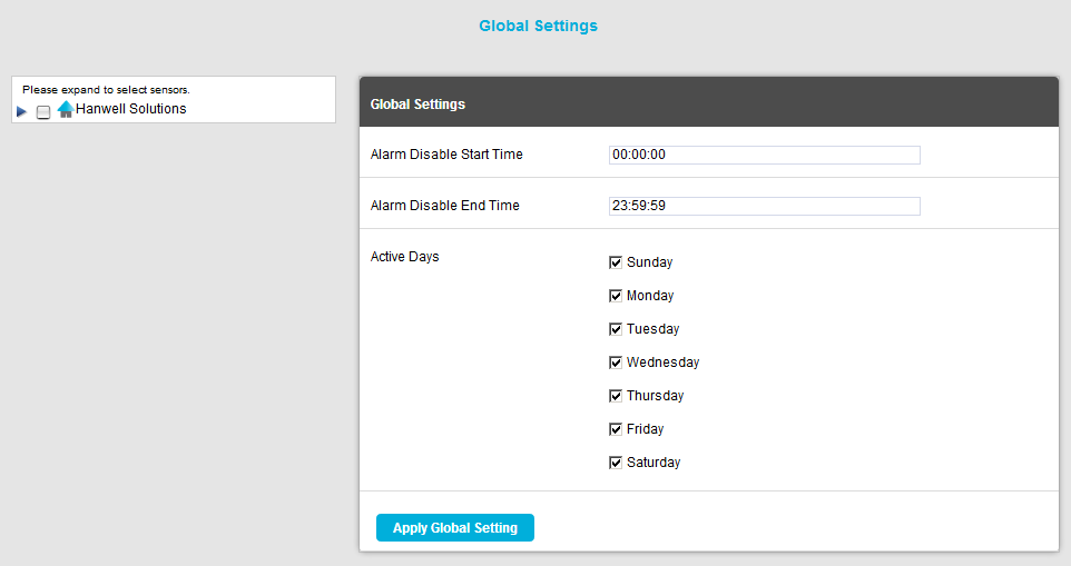
•From this window you can apply the following Alarm settings, globally, to selected Sensors:
➢Alarm Disable Start Time
➢Alarm Disable End Time
➢Active Days
3.Adjust the displayed Alarm settings to the required values.
•These values will be applied globally to the selected Sensors.
| Note: | Times should be entered in the format: HH:MM:SS |
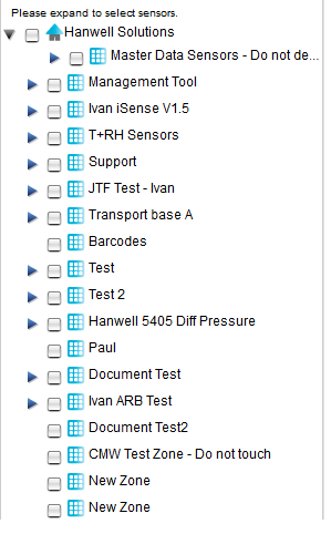
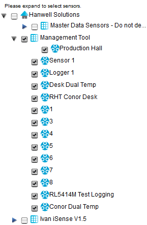
4.In the left-hand 'Please expand to select Sensors' menu, click on the blue arrow to expand the tree and display all Zones associated with the Site by clicking on the blue arrow to the left of the Site name. See Figure 887 below:
Figure 887
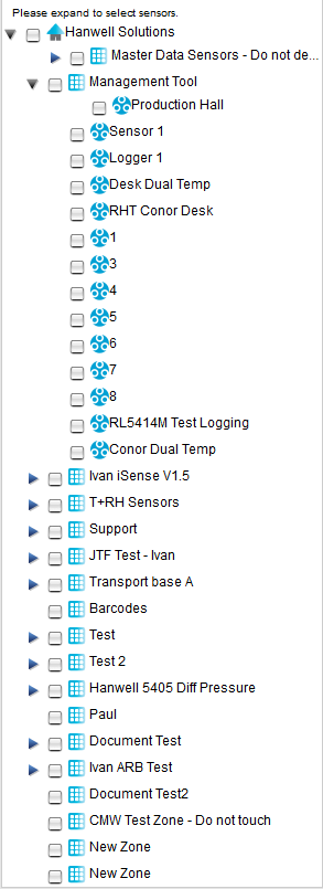
5.Show all of the Sensors/Transmitters in the selected Zone by clicking on the blue arrow to the left of the required Zone's name. See Figure 888 below:
Figure 888
6.To select the Sensors/Transmitters that are to have Global Alarm settings applied:
Either
Click in the tick box next to the Zone name which will select all the Sensors in that Zone
Or
Individually select each required Sensor/Transmitter by clicking in the tick box next to the Sensor/Transmitter's name. See Figure 889 below:
Figure 889
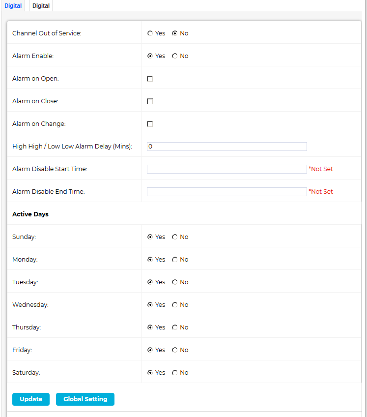
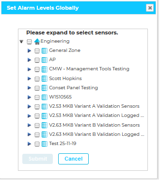
| Note: | In earlier versions of EMS you can also display a separate Set Alarm Levels Globally window, from which you can select the Sensors/Transmitters that are to have Global Alarm settings applied, by clicking on the Global Setting button at the bottom of the Alarm Levels window. See here for an example. |
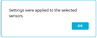
i.Select the Sensor/Transmitters to have Global Alarm settings applied as outlined from Step 4, above, onwards. ➢The Submit button is highlighted. ii.Click on Submit. ➢A dialog box is displayed. See Figure 890 below: Figure 890
iii.Click on OK. |
7.Once you are happy with your Sensor/Transmitter selections, select Apply Global Settings. See Figure 891 below:
Figure 891
•A dialog box is displayed asking you to confirm that you wish to apply the entered Alarm setting values. See Figure 892 below:
Figure 892

➢Click on Yes to update all of the selected Sensors/Transmitters with the entered Alarm setting values.
❖All of the selected Sensor/Transmitters will now be updated with the entered Alarm setting values.
This can be checked by going into the Alarm Level properties of one of the updated Sensor/Transmitters.
➢Click on No to cancel the update.
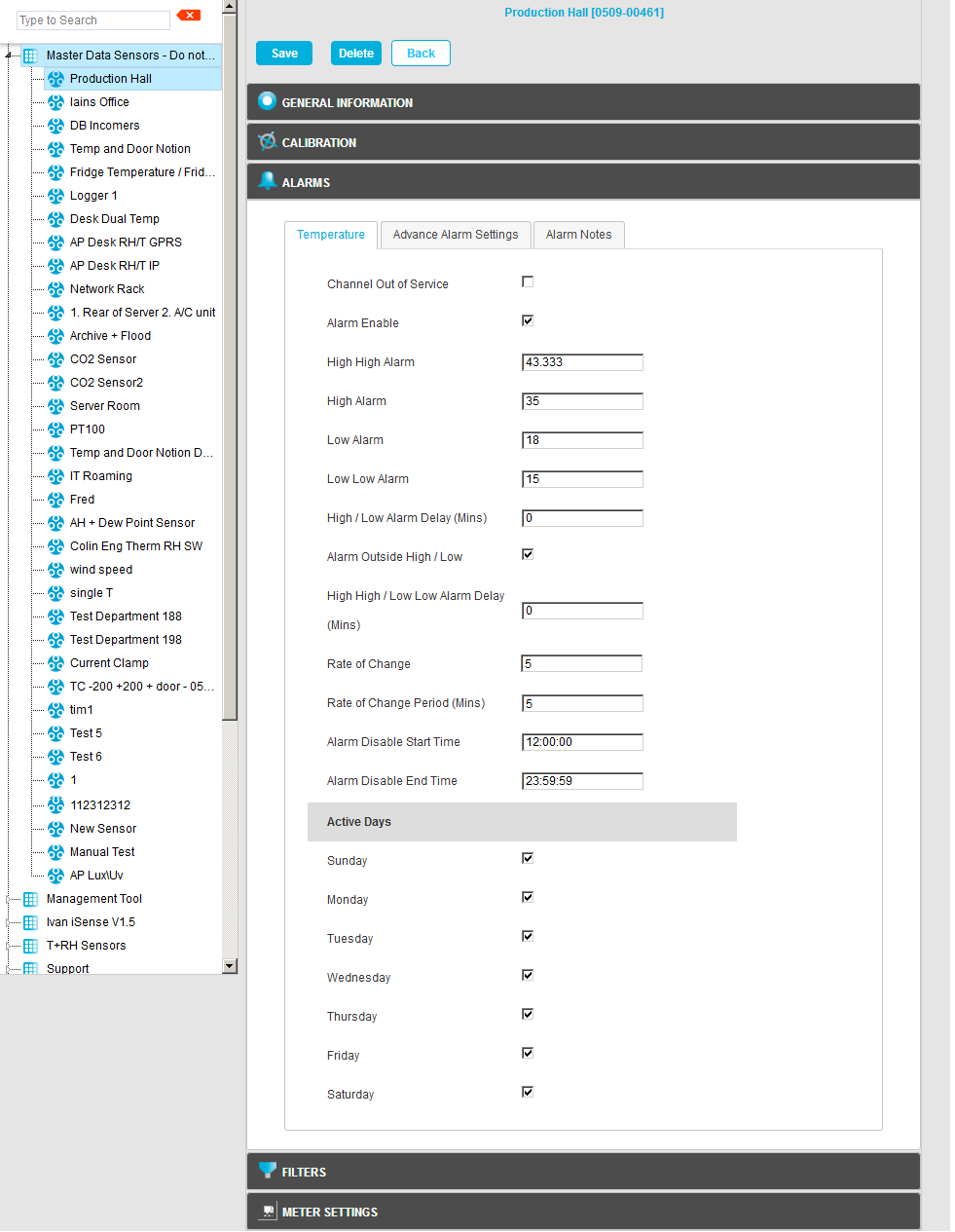
Figure 893 below shows a correctly completed Temperature Alarm Settings page.
| Note: | The actual values will change depending on the measuring parameters, every application will be different. |
Figure 893
| Note: | For earlier versions of EMS, a different window will be displayed, though the Alarm parameters, fields and check boxes will be the same. |
This example shows:
•A High High Alarm of 43.333°C and a Low Low Alarm of 15°C with a delay of 5 minutes.
•The High Alarm is set to 35°C and the Low Alarm to 18°C with a delay of 5 minutes.
•There is a Rate of Change alarm active which will activate if the temperature changes by more than 5°C in 5 minutes.
•All alarms are disabled between the hours of 12:00:00 and 23:59:00 and alarms will be active on every day of the week.
Caution!
Alarm Fatigue
Alarm Fatigue can be a major problem on automated monitoring Systems, especially when the alarms can drive emails or SMS alerts to call out service personnel. Unnecessary alarms, not related to an actual fault, can quickly become a nuisance and affect the perception of all alarms.
There are many circumstances where the conditions of a room or space are not actively controlled and are driven by outside forces such as what’s happening next door or the weather outside. In these cases there is little point setting alarms that would relate to ideal conditions, especially if those conditions couldn’t be continually met on a daily basis.
In these cases it is better to have no alarms set.
The danger of receiving many unnecessary alarms, when nothing can be be done to prevent the re-occurrence of that alarm, is the main cause of alarm fatigue.
Ultimately, Alarm Fatigue runs the grave risk of an alarm in the same System, but this time perhaps relating to a critical space and containing high value objects, being ignored when a vital support System, such as HVAC (Heating Ventilation and Air Conditioning), develops a fault.
We are not suggesting that alarms are never set in these conditions, just that thought and consideration are given during the alarm setting process.