Navigation:
Installation, Configuration and Operation of Hardware > Installation and Configuration of Additional Devices > Hanwell IceSpy > Hanwell IceSpy Sensor-Transmitters >> IceSpy Linear Sensors-Transmitters (1V 5V 10V 4 to 20mA)
IceSpy Linear Sensor-Transmitters (1V, 5V, 10V and 4 to 20mA)

Contents
Linear Sensor-Transmitters are multi-purpose Analogue Sensor-Transmitters within Hanwell's IceSpy series for monitoring multiple parameters such as CO2, Air Flow and Differential Pressure.
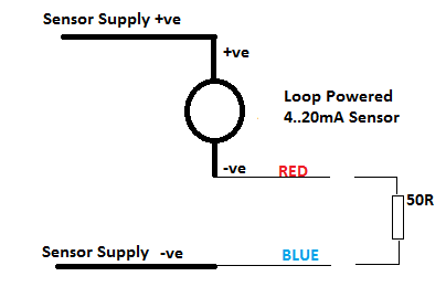
•Connect the supplied cable as follows: Red to +ve, Blue to -ve
•The Input Impedance of the 0 to 10V and 0 to 5V Voltage Input Sensor Transmitters is a nominal 100k.
•The Input Impedance of the 0 to 1V Voltage Input Sensor-Transmitter is 100k.
•They can withstand a permanent over voltage of twice nominal and short term polarity reversal.
•For 0 to 20mA Input Sensor-Transmitter, an internal load resistance of 50R and will normally be connected as shown in Figure 186 below.
| Caution: | The user must ensure that no more than 2V is applied across the Red and Blue Hanwell IceSpy connections under any circumstances. The 50R resistance shown is internal to the device; the User DOES NOT need to add this. |
Figure 186
4-20mA Loop Powered Sensor Connection
With a Gain of 1.0 and Offset of 0 (default), the software will read V or mA directly.
If you wish to display Engineering units other than mV / mA, then the Offset, Gain, Channel Title, Display Units and Precision can be changed as required.
•The Offset is the raw value which will correspond to 0 in the units you are using.
•The Gain is the change in actual value per raw count.
Voltage Input Sensor-Transmitter
Example 1: A 0 to 1V Sensor-Transmitter corresponds to +/-100Bar:
Offset = 0.500
Gain = 100/0.5 = 200
Units = ’BAR’
4-20mA Input Sensor-Transmitter
For 4 to 20mA Input Sensor-Transmitter: Gain = Sensor Range/16, Offset = 4 (Minimum Sensor Reading/Gain).
Example 2: A 4 to 20mA Sensor-Transmitter corresponds to 0 to 100Bar:
Offset = 4.00
Gain = 100/16 = 6.25
Units = ’BAR’
Example 3: A 4 to 20mA Sensor-Transmitter corresponds to 90 to 100Bar:
Gain = (100 – 90)/16 = 0.625
Offset = 4 (90/0.625) = -140
Units = ’BAR’
| Caution: | Applying signal levels over the limits stated above may damage the Unit and will invalidate the warranty. |
Gain and Offset Calculation for IceSpy Linear Sensor-Transmitters
| Note: | If you require the Hanwell Pro Sensor-Transmitters/Data Loggers Gain and Offset Calculator; please CLICK HERE. |
When required, both Offset and Gain can be calculated from the manufacturer’s specifications for the sensor you wish to use, using the Calculator below:
Hanwell IceSpy Linear Sensor Gain and Offset Calculator
|
|||||||||||||||||||||
Enter the values calculated by the above table into the Calibration pane, accessed from EMS's Edit Mode.
•These values are then sent to the Device when it is Synchronised with the EMS Database.