Navigation:
»No topics above this level«EMS OPC UA

Contents
OPC (Open Platform Communications) is a platform independent interoperability standard for the secure and reliable exchange of data in the industrial automation space and in other industries.
The OPC standard is a series of specifications developed by industry vendors, end-users and software developers. These specifications define the interface between Clients and Servers, as well as Servers and Servers, including access to real-time data, monitoring of alarms and events, access to historical data and other applications.
The OPC UA (Unified Architecture), released in 2008, is a platform independent service-oriented architecture that integrates all the functionality of the individual OPC Classic specifications into one extensible framework.
➢ Discovery Server Registration
➢EMS OPC-UA Instance Certificate
➢Client\Server Certificate Trust
➢Inherited Sensor Type Objects
•The OPC-UA interface is expected to interact with clients on a local network or corporate intranet, but not be internet facing.
•EMS OPC-UA runs as a Windows service, the service is similar to the services that make up the back end of EMS.
Two different licences are available for the EMS OPC-UA interface:
•A Perpetual Licence (W955) that does not require internet access once applied.
•An Annual Licence.
Memory: |
Allow 30MB for the Systems background state, plus an additional 1MB for every 10 sensors in EMS. |
CPU: |
For Systems with more than 100 sensors, a dedicated core is recommended. |
HDD: |
Less than 50MB installed. |
Network: |
1GB Ethernet recommended, (minimum for remote SQL), 100MB minimum; EMS OPC-UA requires an internet connection – for licencing purposes – to operate. |
SQL: |
EMS OPC-UA must read a full data set from the database, to update the OPC interface; poor IO bandwidth accessing the SQL |
The System targets the .Net 4.7.2 or later Framework; .Net 4.7.2 or later MUST be installed prior to EMS OPC-UA installation.
EMS OPC-UA will run on Windows 10 Pro or Enterprise; or Windows Server 2012 R2 or later Servers, Server Core Mode Operation is not supported.
| Note: | EMS Servers at EMS Version 1.0.9 or later, will already meet these requirements. |
EMS OPC-UA is intended to be installed and run on the EMS Application Server; it uses the same Service Logon Account as the EMS Data Service.
Where the Service needs to run on another machine, this needs to be accomplished with a W900B installation, and the machine must be within the same domain as the EMS / SQL Servers. In this instance, customers with W900A must switch to W900B using the following process, before installing EMS OPC-UA:
1.If not at the latest version of EMS, upgrade the W900A install to the latest version of W900A.
2.Obtain a Network Login with password set to never expire (see Document: GD6100 - Hanwell EMS User Pre-requisites for details), for use by the EMS Data Service and EMS OPC-UA Service, from your Network Administrator or IT Service Provider.
3.Install W900B on the EMS Server, using the network account obtained above.
| Note: | Operation on a machine remote to the EMS Server may require SQL Server firewall or security software configuration changes to allow access to the EMS Database from the EMS OPC-UA software. Make sure that any firewall on the Remote machine is configured to allow a connection to the SQL Server. |
❖ Contact your Network Administrator or IT Service Provider for any assistance required.
EMS OPA-UA DOES NOT support registration with a Local Discovery Server (LDS). EMS OPC-UA must be the only OPC Server installed on the Host machine.
EMS OPC-UA can be installed directly from the installation media or copied to a folder on the target machine and then installed.
To Install EMS OPC-UA:
1.Log onto the target machine as a Local Administrator.
| Note: | During installation, the Use Account Control window may be displayed; if so, click Yes to continue. |
2.Double click the EmsOpc.msi file to run the installer.
3.Click Next at the Welcome screen.
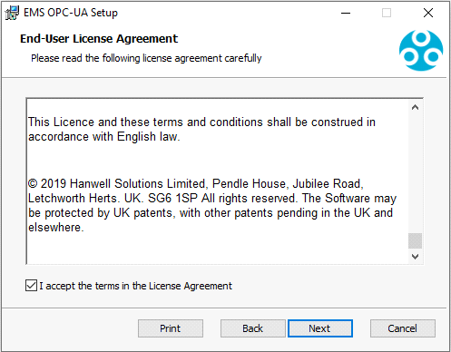
4.Read and accept the licencelicenceconditions. See Figure 1470 below:
Figure 1470
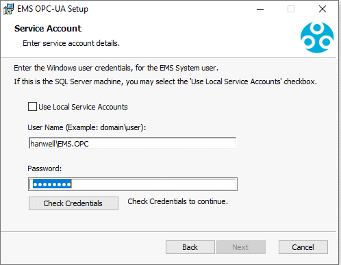
•The Service Account dialogue is displayed. This needs to be completed differently, depending on which W900 variant you have installed. See Figure 1471 below.
5.W900A - If installing EMS OPC-UA on a W900A EMS Server:
i.Select Use Local Service Accounts.
ii.Click Next.
W900B - If installing EMS OPC-UA on a W900B EMS Server:
i.Enter the Username and Password used by the EMS Data Service.
ii.Click Check Credentials to check the login authenticates.
iii.Click Next.
Figure 1471
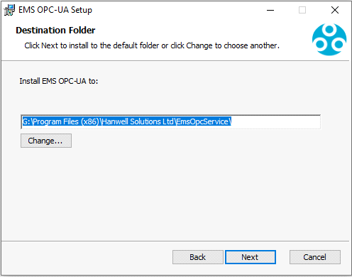
•The Destination Folder window is displayed. See Figure 1472 below.
6.Enter the path to the required Destination folder for EMS OPC-UA.
| Note: | Hanwell recommend using the default path structure, even if the drive is changed. See Figure 1472 below: |
Figure 1472
7.At the following dialogue, click Install to install EMS OPC-UA.
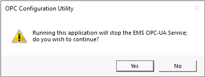
•Once installation has completed; the OPC Configuration Utility needs to be run, to allow setting up the database connection etc.
8.Click Yes at the displayed warning dialogue to run the OPC Configuration Utility. See Figure 1473 below:
Figure 1473
•The OPC Configuration Utility dialog is displayed. See Figure 1474 below:
Figure 1474
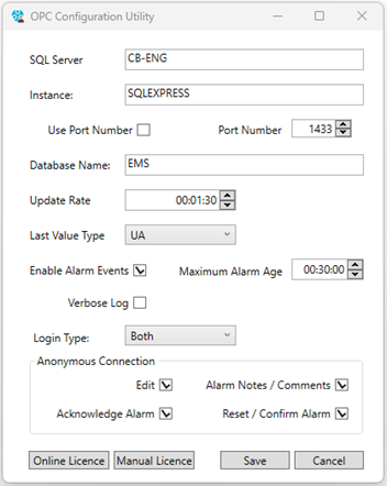
9.Fill out the OPC Configuration Utility dialog's fields:
•SQL Server and Instance or Port Number for the EMS installation.
If you do not know the SQL Server name, run the EMS Config Utility on the EMS Server; the displayed SQL Server combo box will contain:
➢Either
The SQL Server and Instance names seperated by a '\' character.
➢Or
The SQL Server and Port Number seperated by a ', ' character.
•Database Name
The database name used by EMS; for most installations this will be EMS.
•Update Rate
Update Rate is the rate, in hours, minutes and seconds, at which the OPC-UA data is refreshed from the EMS database.
| Note: | Faster update rates increase load on both the Server machine and the SQL Server. |
•Last Value Type
This setting allows EMS OPC-UA to be configured to work with some OPC clients that have been ported from OPC Classic and do not fully support OPC UA data types.
For a Native UA implementation, leave the setting at UA.
If using a Client that does not support the UA DataValue type, Users can select Legacy or Both; see Channel Object below for details.
•Alarm Events
When Enable Alarm Events is checked, OPC UA Alarm Events are enabled for Sensors and Channels and the Maximum Alarm Age numeric up down control is enabled.
➢The Maximum Alarm Age value sets the maximum age of alarms that will be presented to the client when EMS OPC UA starts up.
If the default value of 30 minutes is used, then on start-up, alarms up to 30 minutes old will be activated on the subscribing client.
| Note: | OPC Alarms - High High, High, Low, Low Low, Rate of Change, Battery, Digital and Elapsed, require the OPC-UA Client with OPC-UA Alarms Support. |
•Verbose Log
When Verbose Log is checked, Verbose Log information will be written to a log file, this can assist with debugging.
➢The log file is stored in the software’s Common Application Data folder path.
❖On most machines, this path will be C:\ProgramData\EmsOpcService
If the Common Application Data folder's path has been modified, you will need to obtain the correct path from your Network Administrator or IT Provider.
Version 2.1.0 onwards.
Enables EMS OPC-UA to be configured to accept Anonymous connection; EMS User Logins, (both EMS authenticated and Active Directory authenticated EMS users) or Both.
| Note: | Certificates are still required to sign and encrypt EMS User Login connections. |
•EMS User Edit and Alarm permissions are reflected by EMS OPC-UA.
•Site and Zone permissions are not currently reflected by EMS OPC-UA, i.e. Users have View access to all sensors, as with the previous Anonymous Only connection versions of EMS OPC-UA, (this is because the Sensor Node Address Space is built before the OPC-UA Client connection is made).
Version 2.1.0 onwards.
EMS OPC-UA can be configured to restrict Edit and Alarm actions for Anonymous connections.
•Edit
When checked, Anonymous connections can edit Writable Nodes.
See Client Writable Nodes for additional information on Writeable Nodes.
•Alarm Notes / Comments
When checked, Anonymous connections can OPC-UA Add Comments to alarms, which adds notes to the Alarm Log Audit Trail in EMS.
•Acknowledge Alarm
When checked, Anonymous connections can Acknowledge Alarms.
•Reset / Confirm Alarm
When checked, Anonymous connections can OPC-UA Confirm alarm events, which resets the alarm event in EMS.
•Licencing
i.Click the Online Licencelicensebutton.
•The Activate Online dialog is displayed. See Figure 1475 below:
Figure 1475
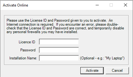
ii. Enter your EMS OPC-UA LicencelicenseID and Password, Installation Name can be left blank; click Activate.
•An Activation message box will display, stating Activation Successful!
10.Click OK.
•A second message box will display, stating LicencelicenseActivated.
11.Click OK.
•You are returned to the OPC Configuration Utility dialog.
Endpoint Connection and Security
The following information is intended to help the User setup a connection from an OPC UA Client to the EMS OPC-UA Server. EMS OPC-UA will only work with an OPC UA Client; OPC Classic Clients that require DCOM WILL NOT connect to an EMS OPC-UA server.
•Server Configuration Name: Hanwell
•Endpoint URL: opc.tcp://<hostname>:48030
➢Replace <hostname> with the Resolvable Host Name or IP Address of the EMS OPC-UA machine.
If you do not know these details, you will need to ask your Network Administrator or IT Service Provider.
By default, EMS OPC-UA uses the OPC UA Basic256Sha256 Security Policy Profile for Connection Signing and encryption.
EMS OPC-UA manages certificates using its Certificate Store in the software’s Common Application Data folder path; on most machines the path will be: C:\ProgramData\EmsOpcService\pkiserver
| Note: | If the Common Application Folder path has been modified, you will need to obtain the correct path from your Network Administrator or IT Service Provider. |
EMS OPC-UA Instance Certificate
If there is no Application Instance Certificate present, the EMS OPC-UA Service will automatically create one.
The Application Instance Certificate files are stored in the 'own' folder path: C:\ProgramData\EmsOpcService\pkiServer\own
•The folder has 'certs' and 'private' sub-folders, containing Certificate and Private Key files.
If you wish to use your own Application Instance Certificate:
1.Stop the EmsOpcService.
2.Delete the automatically created Certificate and Private Key files.
3.Place the required Certificate file in the own\certs sub-folder and the Private Key file in the own\private sub-folder.
4.Restart the Service.
| Note: | You can stop the Service by running the OPC.ConfigurationUtility. Make the files changes as described, then exit the OPC.ConfigurationUtility to restart the Service. |
Client\Server Certificate Trust
When a client connects to the EMS OPC-UA Server for the first time, the Client will need to be configured to trust the Server certificate.
The actions required to trust a Server Certificate at the Client cannot be detailed in this Help file as they will be specific to the User’s client. However, many test clients will ask you to accept the certificate, presented by EMS OPC-UA Server, when the you initially connect the Client to the Server; as you have knowingly initiated the connection, the safest and easiest way to proceed is simply to accept the Server's certificate at this point.
•When a Client connects to the EMS OPC-UA Server for the first time, the Server will not trust the Client’s Certificate and the connection will be rejected.
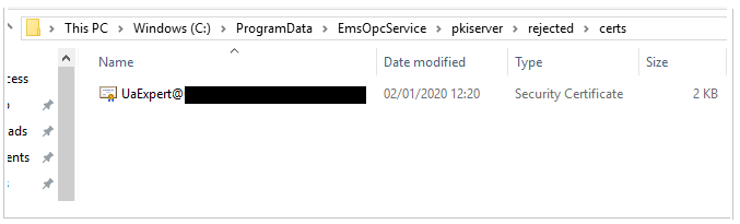
•The Server makes a copy of rejected Certificates, so these can easily be moved to the trusted folder.
•Rejected Client Certificates are stored in the Rejected Certificates folder:
C:\ProgramData\EmsOpcService\pkiServer\rejected\certs
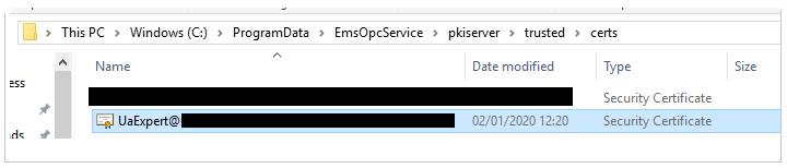
•To trust a Rejected Certificate, move the Certificate file to the Trusted Certificates folder:
C:\ProgramData\EmsOpcService\pkiServer\trusted\certs
Example Test Client
The following information details creating a Test Client Connection, using Unified Automation’s UaExpert Client to test an EMS OPC-UA connection.
•The Client Software and User Documentation can be found on the Unified Automation website:
https://documentation.unified-automation.com
There are a variety of OC UA test clients available. Each client will obviously have a different User Interface; however, all clients will require similar configuration settings to those described below.
| Note: | Hanwell recommend that Users initially test the Connection on the same machine that the EMS OPC-UA server is running on, to bypass potential issues with Firewalls etc. |
To use the UaExpert Client to test an EMS OPC-UA connection:
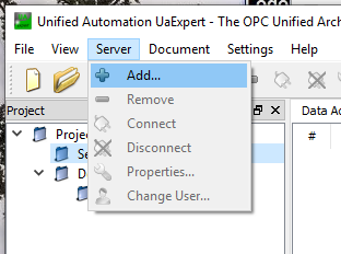
1.Run the Unified Automation UaExpert Client.
2.From the Server menu item, click Add… See Figure 1476 below:
Figure 1476
•The Add Server window is displayed. See Figure 1477 below:
Figure 1477
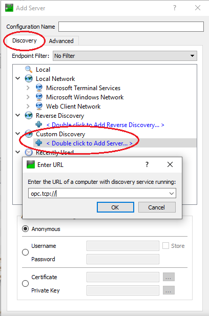
3.Click on the Discovery tab in the Add Server window. See Figure 1477 above.
4.Double click on the < Double click to Add Server…> entry in the Discovery tab pane's Custom Discovery entry. See Figure 1477 above.
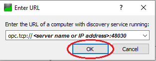
•The Enter URL window is displayed. See Figure 1477 above.
5.Enter the URL connection and Port Number for the server as: opc.tcp://<server name or IP address>:48030
•To test locally on the EMS OPC-UA Server machine, enter the URL connection and Port Number for the server as: opc.tcp://localhost:48030
6.Once the Server's URL has been entered, click on OK. See Figure 1478 below:
Figure 1478
7.In the Discovery tab's pane in the Add Server window, expand the added Server URL's entry in the Custom Discovery list and select Basic256Sha256 – Sign and Encrypt. See Figure 1479 below:
Figure 1479
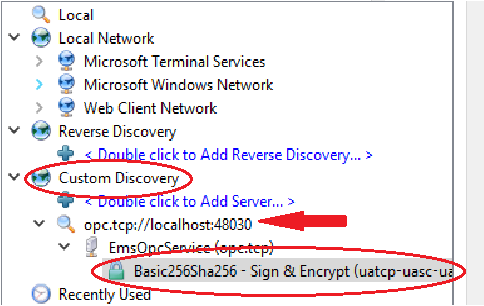
8.Click on OK.
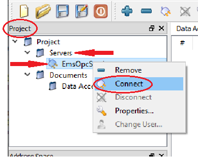
9.In the Unified Automation UaExpert Client's main window, right click on the EmsOpcService entry under Servers in the Project panel.
10.Click on Connect in the displayed drop-down menu. See Figure 1480 below:
Figure 1480
•The Certificate Validation window is displayed. See Figure 1481 below:
Figure 1481
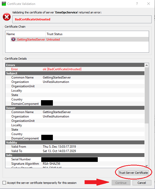
| Note: | The actual information shown in the Certificate Validation window will differ from System to System. |
11.Click the Trust Server Certificate button.
•The Continue button is highlighted.
12.Click on the Continue button.
•The Log panel at the bottom of the main window will now display a security error from the EMS OPC-UA Server, because the Client Certificate now needs to be trusted by the EMS OPC-UA Server.
13.On the EMS OPC-UA Server, open a File Explore window and navigate to the Server's Rejected Certificates folder (C:\ProgramData\EmsOpcService\pkiServer\rejected\certs). See Figure 1482 below:
Figure 1482
14.Move the rejected UaExpert Certificate to the Server's Trusted Certificates folder:
C:\ProgramData\EmsOpcService\pkiServer\trusted\certs).
See Figure 1483 below:
Figure 1483
•See Trust at Server above.
15.In the Unified Automation UaExpert Client's main window, right click on the EmsOpcService entry under Servers in the Project panel.
16. Click on Connect in the displayed drop-down menu. See Figure 1484 below:
Figure 1484
•The UaExpert Client will now connect to the the EMS OPC-UA server.
To See Data for Sensors:
1.Expand the Sensors folder in the Address Space panel.
2.Select a Sensor and drag it to the Data Access View panel.
3.Click Yes on the Recursively Add Nodes dialog.
•The Sensor data will be displayed. See Figure 1485 below:
Figure 1485
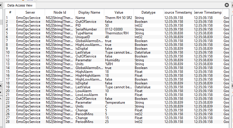
•To view the reading and timestamp for LastVaue nodes, double click in the Value field, where it says “Type cannot be displayed” for the required LastVaue node.
It is possible to disable Endpoint Security for testing purposes:
1.Navigate to the EMS OPC-UA executable folder; the default executable path is:
C:\Program Files (x86)\Hanwell Solutions Ltd\EmsOpcService
| Note: | If you changed the executable path during install, you will need to navigate to the path set during install. |
2.In the executable folder, open the EmsOpcService.exe.config file with a text or EML editor.
3.Find the http://opcfoundation.org/UA/SecurityPolicy#None Security Profile element and set its child Enabled element to true ie:
<SecurityProfile>
<ProfileUri>http://opcfoundation.org/UA/SecurityPolicy#None</ProfileUri>
<Enabled>true</Enabled>
</SecurityProfile>
| Note: | Ellab Monitoring Solutions Ltd strongly recommend that SecurityPolicy#None is disabled during normal operation. |
During System development, Hanwell strongly recommend using a pre-built Unified Architecture Client, such UaExpert from Unified Automation GmbH, to initially test the connection and show the Sensor Nodes available in EMS OPC-UA.
OPC-UA has an Address Space made up of Nodes; each Node is an Object, Variable, Method or View that can be accessed by Clients and Servers.
EMS OPC-UA creates Objects made up of various Data Type Items, representing the Sensors and their data, contained within an EMS System.
This Object will be used in the Sensor Objects to represent Channel information.
•A Channel contains various Variable Type Children:
Channel Alarm: |
Optional OffNormalAlarmType, raises Channel Alarm Events. |
GlobalAlarmsEnable: |
Bool global enable state for all Level and Rate of Change alarms on the Channel. |
HighLowAlarmsEnable: |
Bool global enable state for High and Low Level alarms on the Channel. |
High High, High, Low: |
Optional Analogue Alarm Level values. |
HighHighLowLowAlarmDelayMins: |
Optional UInt16 Alarm Delay in minutes. |
RateOfChangeAlarm: |
Optional RateOfChangeAlarm object. |
LastValue: |
Optional DataValue type that contains the last data point, Value and Date time available for the Channel. •Date Time is UTC, as per OPC-UA specification. This node is not present, if the Last Value Type is set to Legacy in the Configuration Utility. |
LegacyLastValue: |
Optional LegacyLastValue object. |
Parameter: |
String identifying the parameter read by the channel, e.g. Temperature. |
Units: |
Optional String Unit Type, e.g. C. |
IsDigital: |
Bool identifying if the Channel is a digital channel. |
OutOfService: |
Bool identifying Channel Service State. |
Change: Analogue Change Alarm Level.
PeriodMins: UInt16 Change Alarm Period in minutes.
LegacyLastValue: |
LegacyValue analogue last data point available for the channel. |
LegacyTime String: |
Date time for the last data point available for the channel converted to the local time zone at the sensor site. String type, because legacy clients do not always handle date types. |
Sensor Object is the Base Sensor type; other Sensor types inherit from the Sensor Object.
•The Sensor type Object represents Loggers in the Address Space.
Sensor has the following Object and Variable Type Children:
➢Channel1 |
Optional Channel objects representing channel information, see above for details. |
➢Name: |
String Sensor Name. |
➢OutOfService: |
Bool State identifier. |
➢SerialNumber: |
String Sensor Hardware Serial Number. |
➢UniqueID: |
UInt32 unique Identifier Number for the Sensor. |
There are three Sensor types that inherit from the Base Sensor type:
•HanwellProTransmitter
Represents Hanwell ML/RL series 2000, 4000, 5000, and 5400 Sensors.
Additional children are:
➢DigitalInput: Optional bool.
➢PID: Byte - Hanwell Radio ID Number; Range 1 to 254.
➢Sensor Alarm: Optional OPC UA OffNormalAlarmType, raises Sensor Elapsed Time and Battery Alarm Events.
•IceSpyTransmitter
Represents IceSpy Pro, IceSpy Transport, IceSpy Legacy, and Selsium transmitters.
Additional children are:
➢BatteryLevel: Byte - Level 0 to 5
➢Sensor Alarm: Optional OPC UA OffNormalAlarmType, raises Sensor Elapsed Time and Battery Alarm Events.
•iSense
Additional children are:
➢LogInterval: UInt16 minutes.
➢TransmitRate: Uint16 minutes.
➢Sensor Alarm: Optional OPC UA OffNormalAlarmType, raises Sensor Elapsed Time and Battery Alarm events.
The following table identifies which Nodes are writable by the OPC UA Client:
CHANNEL NODES |
||
|---|---|---|
Node |
Writable |
Comment |
Channel Alarm |
No |
Acknowledge, Add Comment, and Confirm Methods available. |
GlobalAlarmsEnable |
Yes |
|
HighAlarm |
Yes |
|
HighHighAlarm |
Yes |
|
HighHighLowLowAlarmsDelayMins |
Yes |
|
HighLowAlarmsDelayMins |
Yes |
|
HighLowAlarmsEnable |
Yes |
|
IsDigital |
No |
|
LastValue |
No |
|
LegacyLastValue |
No |
|
LowAlarm |
Yes |
|
LowLowAlarm |
Yes |
|
OutOfService |
No |
|
Parameter |
No |
|
RateOfChangeAlarm |
Yes |
Change and PeriodMins can be set. |
Units |
No |
|
SENSOR NODES |
||
Node |
Writable |
Comment |
Name |
No |
|
OutOfService |
No |
|
SensorAlarm |
No |
Acknowledge, Add Comment, and Confirm Methods available. |
SerialNumber |
No |
|
TypeName |
No |
|
UniqueID |
No |
|
Hanwell Pro - DigitalInput |
No |
|
Hanwell Pro - PID |
No |
|
IceSpy - BatteryLevel |
No |
|
iSense - LogInterval |
No |
|
iSense - TransmitRate |
No |
|
•EMS OPC-UA indicates Address Space changes to Clients using the OPC UA specified ModelChangeEvent and NodeVersion property.
•EMS OPC-UA will update the NodeVersion property and fire a ModelChangeEvent, when a Node is added to, or removed from, the Address Space during normal operation.
•Clients needing to automatically update Node changes should subscribe to ModelChangeEvents, so that they are informed of changes and can then refresh their Model View.
Historical data is available for the Channel Object’s LastValue Variable.
• OPC Historical Data Access provides Read Only access to sensor readings and requires the OPC-UA Client with OPC-UA HDA support.
| Note: | Because EMS stores all data received from transmitters (typically, every 3 or 5 minutes for Hanwell Pro or every minute for IceSpy), reading long periods of historical data can take several minutes to complete. |
•If you are using Unified Automation’s UaExpert Client to test EMS OPC UA, you can view historical data in the History Trend View as follows:
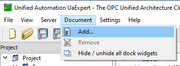
i.Select Document > Add... from the UaExpert menu bar. See Figure 1486 below:
Figure 1486

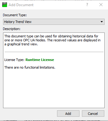
ii.From the displayed Add Document window, select History Trend View from the Document Type: drop down, then click Add. See Figure 1487 below:
Figure 1487
iii.Expand the Sensors folder in the Address Space panel; expand the the required Sensor's entry; then the required Channel's entry.
iv.Select and drag the Channel’s LastValue to the left-hand box, and drop it under Server, in the History Trend View panel’s Configuration section. See Figure 1488 below:
Figure 1488
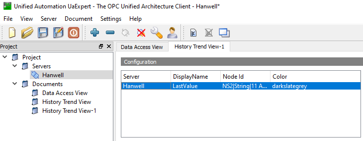
•If required, expand other channels and drag and drop their LastValue variables to the Configuration box.
v.Use the Start Time and End Time fields to set the required history data span; then click Update to read the historic data from EMS.
vi.The historic data will be read and displayed on the graph and in tabular format, in the History Data section’s tabs.
Sensor and Channel Alarm Events are available for Client Subscription.
If there are multiple active Sensor or Channel Alarms, all active alarms will be represented by a Sensor or Channel Alarm.
EMS OPC-UA provides the client with three OPC-UA Alarm Event actions, which map to EMS alarm actions:
•Acknowledge:
Acknowledges the alarm(s) and writes any User entered comment as an EMS Alarm Note entry.
➢EMS requires an Alarm Note on Alarm Acknowledgement. If no comment is made, EMS OPC-UA will insert “No OPC-UA Acknowledge comment set.” as the alarm(s) note(s).
•Comment:
Adds the User entered comment to the selected alarm(s) notes.
•Confirm:
Reset's the alarm(s) and writes any User entered comments as EMS alarm note entries.
➢EMS requires an Alarm Note on Alarm Reset. If no comment is made, EMS OPC-UA will insert “No OPC-UA Confirm comment set” as the alarm(s) note(s).
➢If an unacknowledged Alarm is confirmed, the alarm will be Acknowledged as well as Reset in EMS.
•The above Alarm Event actions will result in “EMS OPC-UA” being recorded in the Acknowledged By and Note By fields for Anonymous connections; for EMS User connections, the EMS Username will be recorded.
•If you are using Unified Automation’s UaExpert client to test EMS OPC-UA, you can view alarms in Event View as follows:
i.From the UaExpert menu bar, select Document > Add.... See Figure 1489 below:
Figure 1489
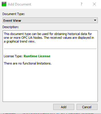
ii.From the displayed Add Document window, select Event View from the Document Type: menu, then click Add. See Figure 1490 below:
Figure 1490
iii.Expand the Sensors folder in the Address Space panel.
iv.Select and drag the required sensor to the box under the Event View panel’s Configuration section. See Figure 1491 below:
Figure 1491
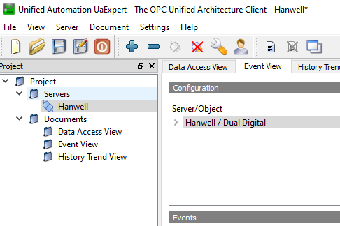
➢If required, drop other sensors into the Configuration box.
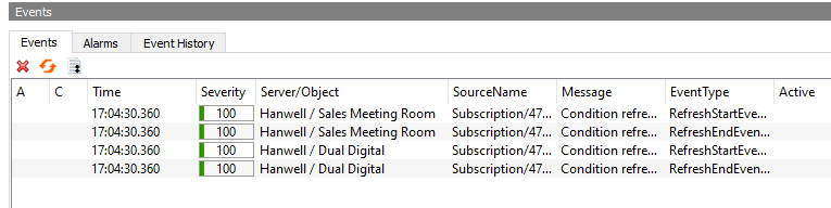
➢Subscribed Events can be seen under the Events Panel’s Events tab. See Figure 1492 below:
Figure 1492
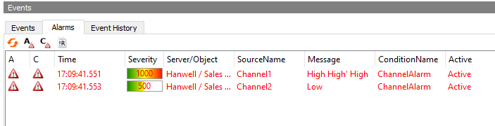
➢When an Alarm occurs it will be displayed in the Events panel’s Alarms tab. See Figure 1493 below:
Figure 1493
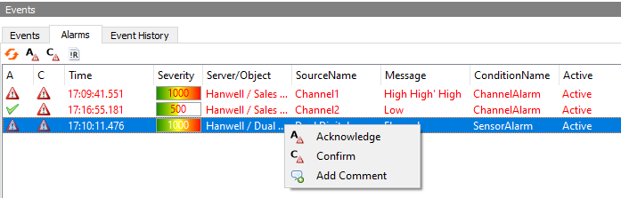
v.Right clicking an alarm allows the user to Acknowledge, Comment, and Confirm Alarms from the displayed drop-down menu. See Figure 1494 below:
Figure 1494
vi.Click on the required option.
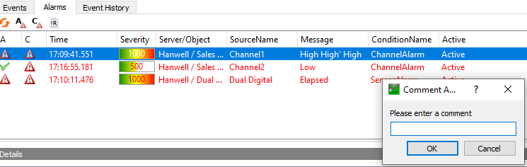
➢If you select Add Comment, a window will be displayed where you can enter a comment. See Figure 1495 below:
Figure 1495
vii. Click OK.
➢The corresponding action – as described above – will be actioned on the EMS System.
➢To view the results of Acknowledging, Commenting, or Confirming an Alarm:
a)View the EMS Alarm Log.
b)Click on the Memo field for the Alarm.
❖A window will open showing information about, and the comments added to, the Alarm.
Version 2.1.0 onwards:
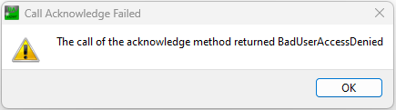
If the connected User does not have permission, the BadUserAccessDenied status will be returned. See Figure 1496 below.
| Note: | If a user with the Reset permission but without the Acknowledge permission, tries to Confirm an unacknowledged alarm, the BadUserAccessDenied status will also be returned; this is because, alarms have to be Acknowledged before Rest in EMS. See Figure 1496 below: |
Figure 1496
Version 2.1.0 onwards.
EMS OPC-UA can be configured with the OPC Configuration Utility to accept Anonymous and Authenticated EMS User connections, see Login Type and Anonymous Login (Allowed Actions) for configuration details.
•If you are using Unified Automation’s UaExpert Client to test EMS OPC-UA, you can test Anonymous and EMS User connections using the UaExpert Server connection.
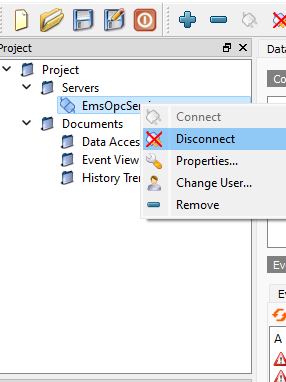
•If UaExpert is connected to the EMS OPC-UA Server, then it must first be disconnected before changing User as follows:
i.In the Project panel, select Servers.
ii.Right click on the displayed EmsOpcService entry.
iii.Select Disconnect from the displayed menu.
➢See Figure 1497 below:
Figure 1497
User connections are set in the Servers settings Properties dialog as follows:
1.In the Project panel menu list, right-click the EmsOpcService entry under Servers. See Figure 1497 above.
2.Click Properties; the Server Settings window is displayed. See Figure 1498 below:
Figure 1498
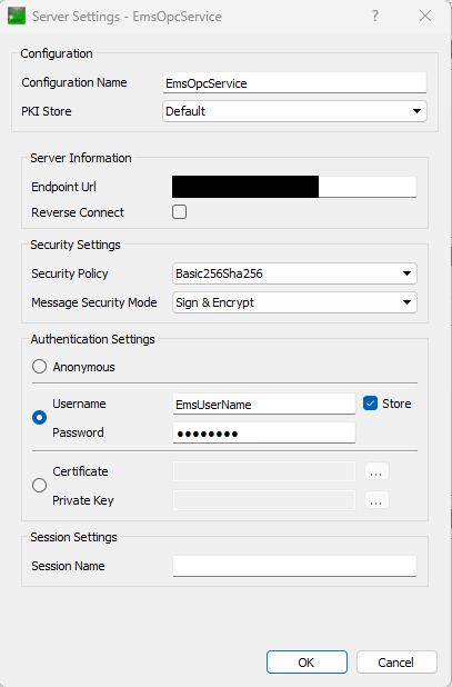
4.In the displayed Server Settings window, click on the Username radio button.
5.Enter the required EMS username and password into their respective fields. See Figure 1498 above.
•You may select Store to save the Username if desired, in either case, the password will not be saved when UaExpert is closed.
6.Click OK to close the dialog.
7.In the Project panel menu list, right-click the EmsOpcService entry under Servers.
8.Select Connect from the displayed menu. See Figure 1499 below:
Figure 1499
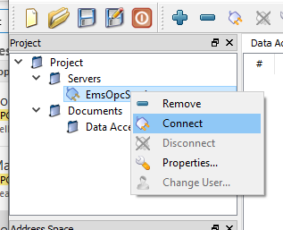
•UaExpert will connect as the EMS user entered above.
•If you create an alarm in EMS and Acknowledge, add Comments or Confirm the Alarm with OPC-UA, the EMS User will be entered in the Alarm Log Audit Trail.
•If the OPC-UA connection is Anonymous, then EMS OPC-UA will be entered as the User in the Alarm Log Audit Trail.