Navigation:
Installation, Configuration and Operation of Hardware > Installation and Configuration of Additional Devices > Hanwell iSense >> Setting Up iSense Hardware
Setting Up iSense Hardware

Contents
The iSense Unit’s front panel is fastened by four screws situated in each corner on the front of the device.
Using a screwdriver, unscrew the four screws and lift off the front panel. See Figure 194 below:
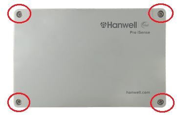
Figure 194
iSense – Front Panel
•Once the front panel has been removed, the iSense circuit board and battery holders become accessible. See Figure 195 below:
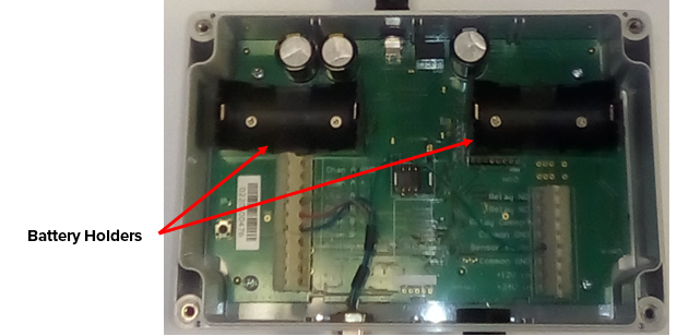
Figure 195
iSense Unit – Front Panel Removed
Connecting the Aerial
There are three types of aerials that can be attached to iSense Units:
•Articulated, knuckle jointed, aerial (G205). See Figure 196 below:
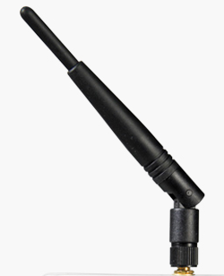
Figure 196
➢Can be used indoors or outdoors
•Dome aerial (G455). See Figure 197 below:
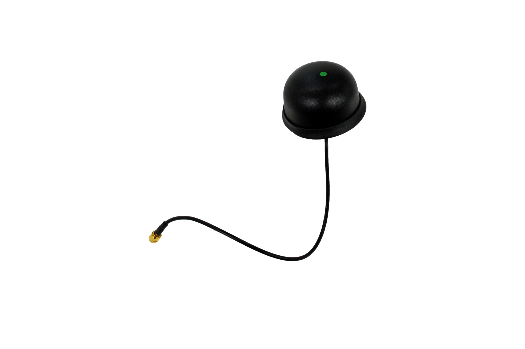
Figure 197
➢Suitable for use outdoors
•Remote mounted Flat Blade aerial (AM36913). See Figure 198 below:
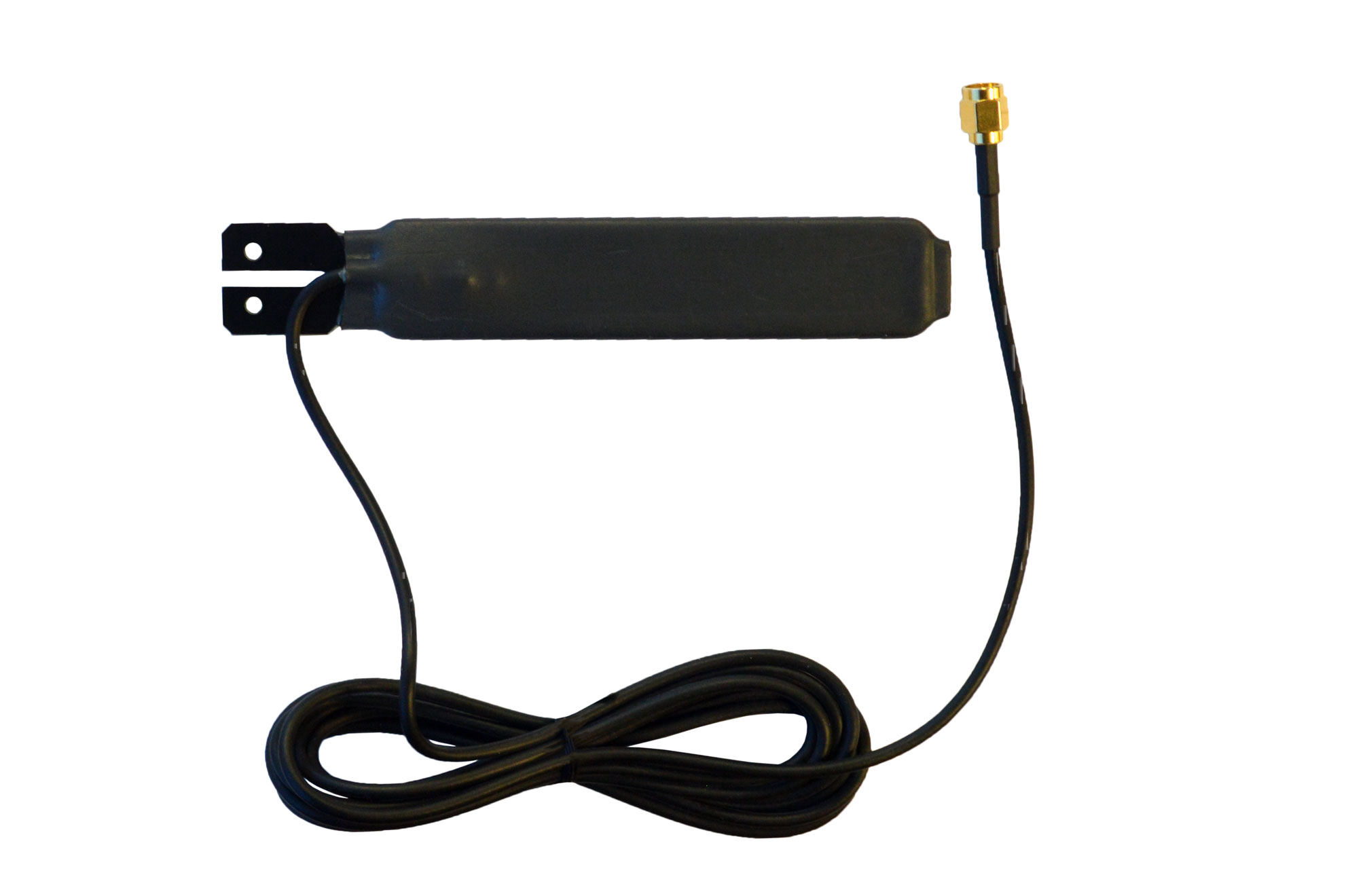
Figure 198
➢Suitable for indoor use only.
➢Extended antenna for low signal areas.
•Choose the aerial that best suits the environment where the iSense unit will be located and simply screw it or the aerial's cable connector, into the brass coloured Aerial connection found on the top of the iSense Unit.
| Caution: | Do not use excessive force tightening the aerial connection, finger tight is adequate. |
•The Aerial/Unit should be positioned to ensure a good RF signal.
Compatible Aerial Types
iSense Transmitter/Sensor |
Compatible Aerial Type(s) |
IS01-BN |
G205, G455 or AM36913 |
IS02-BN |
G205, G455 or AM36913 |
IS04 BR |
G205 or G455 |
IS04 BN |
G205 or G455 |
IS05-BN |
G205 or G455 or AM36913 |
IS06 BN |
G205 or G455 or AM36913 |
IS07 BN |
G205 or G455 or AM36913 |
IS08 BN |
G205 or G455 or AM36913 |
IS09 BN |
G205 or G455 or AM36913 |
Power
| Caution: | Fit sensors and aerial before connecting power or batteries. See Figure 199, Figure 200, Figure 201 and Figure 202 below. |
Inserting the Batteries
| Note: | The IS08 unit has no provision for battery power, being powered only from an external power supply. |
| Note: | If you have ordered an External Power Unit, you will be provided with a 12VDC Desktop Power Supply (G422) instead of batteries. See Figure 199 below: |
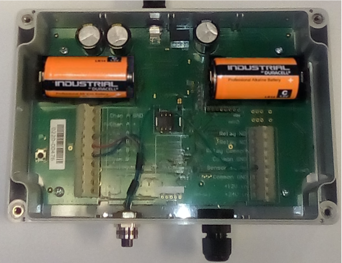
Figure 199
Batteries Inserted
1.Remove the Unit’s front cover.
2.Insert the 2 x 1.5V Alkaline C cell batteries (88702) or 2 x 3.6v Lithium C cell battery (88704) into the battery holders. See Figure 199 above.
| Caution: | Be sure to insert the batteries in their correct orientation – the correct polarity is embossed on the battery holders. |
External Power Supply (12VDC Power Supply Unit or 12VDC/24VDC Vehicle Supply)
| Caution: | Vehicle power should be sourced from as ‘clean’ a supply as possible. If using an External Power Supply, DO NOT fit batteries to the holders. |
| Note: | The 12VDC or 24VDC external supply is protected by a 0.5A fuse. |
Connecting the Power Supply Cable (if External Power Supply specified):
1.Remove the Unit’s front cover. See Removing the Front Panel above.
2.Loosen the right-hand input gland. See Figure 200 below:
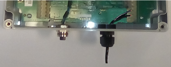
Figure 200
3.Feed the 12 or 24V Power Supply Cable through the right-hand cable gland.
4.Thread the exposed wires up the gland until there is enough length for the wire to reach the right-hand connector block.Figure 202 below:
5.Tighten the gland.
6.Using a screwdriver, press down in turn on the terminal block’s Terminal Release Levers to open the Common GND (-ve) and +12V In or +24V In (+ve) connectors. See Figure 201 below:
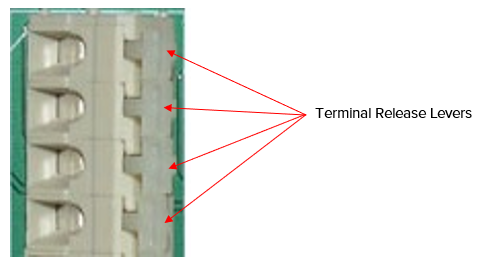
Figure 201
7.Thread the exposed ends of the Power Supply wires into the relevant open terminals (+12V or +24V to take account of the Power Supply voltage) and release the Terminal Release Levers.. See Figure 202 below:
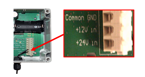
Figure 202