Navigation:
Installation, Configuration and Operation of Hardware > Installation and Configuration of Additional Devices > Hanwell iSense > Installing Sensors/Probes to iSense Transmitters >> Attaching 'Wired' Sensors/Probes to iSense Transmitters
Attaching 'Wired' Sensors/Probes to iSense Transmitters

Contents
To Attach ‘Wired’ Sensor(s)Probe(s) to the iSense Unit:
1.Remove the iSense Unit’s front cover.
•See Removing the Front Panel.
2.Loosen one of the input glands.
•The number of glands will depend on the number of Channels the Unit has and whether the Unit is supplied with an external power supply.
•Start with the left-hand gland for the first probe to be added. See Figure 214 below:
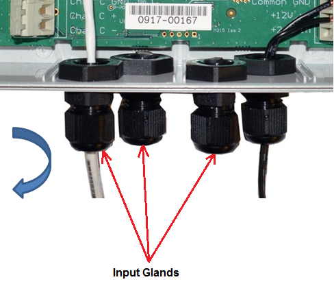
Figure 214
Loosening the Input Gland(s)
3.Thread the probe’s exposed wires through the gland until there is enough length for the wire to reach the Sensor/Probe Connection Terminal at top of the circuit board. See Figure 215 below.
4.Tighten the gland.
5.Using a screwdriver, press down on the Chan A GND Terminal Release Lever to open the Chan A GND (-ve) terminal. See Figure 215 below:
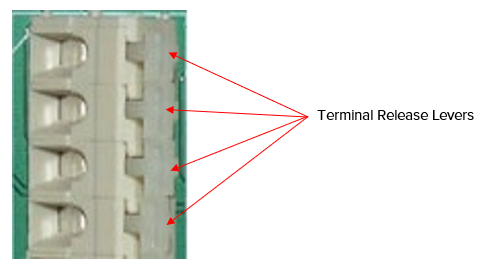
Figure 215
6.Thread the exposed end of the probe’s white wire and the shield into the open Chan A GND terminal. See Figure 216 below.
7.Release the lever.
8.Using a screwdriver, press down on the Chan A + Terminal Release Lever to open the Chan A + (+ve) terminal. See Figure 214 above.
9.Thread the exposed end of the red wire into the open Chan A + terminal. See Figure 216 below.
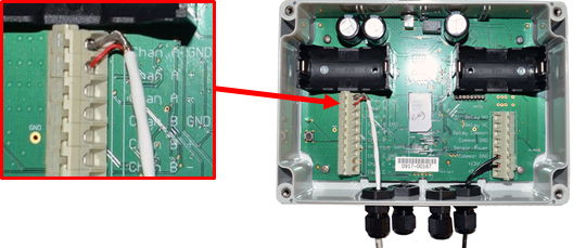
Figure 216
➢Note the Thermistor Probe’s shield connected to the Chan A GND terminal along with the white wire in this example.
10.Release the lever.
11.Repeat Steps 2 – 10 for any further probes for 2 or 3 Channel iSense devices; connecting additonal probes to Chan B GND/Chan B + and Chan C GND/Chan C + terminals respectively. See Table below:
Thermistor Type |
Chan A + (+ve) EMS CH1 |
Chan A GND |
Chan B + (+ve) EMS CH2 |
Chan B GND |
Chan C + EMS CH3 |
Chan C GND |
Single Channel |
Wired probe’s |
Wired probe’s |
none |
none |
none |
none |
Dual Channel |
First Wired probe’s |
First Wired probe’s |
Second Wired probe’s |
Second Wired probe’s White wire |
none |
none |
Triple Channel |
First Wired probe’s |
First |
Second Wired probe’s |
Second Wired probe’s |
Third Wired probe’s |
Third Wired probe’s |
Table
| Note: | The Thermistor Probe(s) shields for the IS02 Unit should also be connected to the Chan A GND (for 1st probe), Chan B GND (for 2nd probe) and Chan C GND (for 3rd probe) terminals. |
| Note: | Standard Thermistors cable sheath = White Waterproof Thermistors cable sheath = Orange |