Navigation:
Installation, Configuration and Operation of Hardware > Installation and Configuration of Additional Devices > Hanwell iSense >> Installing Sensors/Probes to iSense Transmitters
Installing Sensors/Probes to iSense Transmitters

Contents
Installing the Sensors/Probes
iSense Sensors/Probes are installed as follows:
Either:
Attached to sockets on the iSense Units via, either directly attached or via, optional, extension cables.
Or:
Wired into the iSense Unit’s (either integral to the sensor/probe or extension cables attached to the sensor/probe by the Customer) circuit board through glands in the Unit’s case. Click HERE for installation instructions for such ‘wired’ probes.
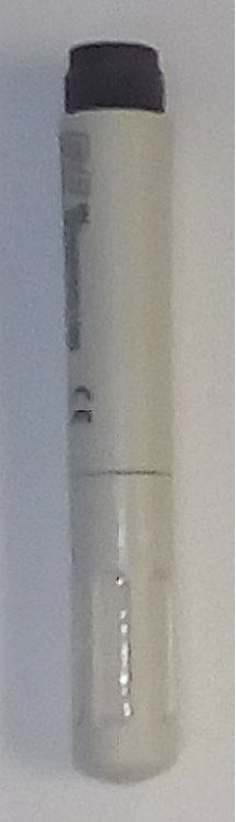
Figure 203
EE07 RH/T Probe (J140)
•The Temperature and Humidity Probe’s threaded end is screwed into the socket on the base of the Unit. See Figure 204 below:
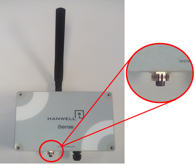
Figure 204
| Note: | Though the sensors/probes are typically mounted directly onto the case via the socket, the sensor/probe can also be mounted remotely using the Y41-1 (1 metre length), Y421-3 (3 metre length) or Y421-5 (5 metre length) extension cables. |
| Note: | Above procedure also works for EE07 (J223) probe. |
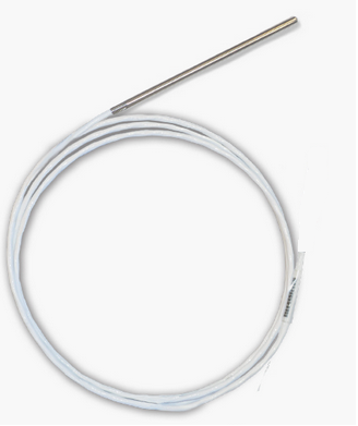
Figure 205
Thermistor probe (J095)
•The Thermistor Sensor/Probes (J095) are connected to the Transmitter Unit as outlined HERE.
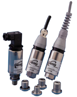
Figure 206
•The GEMS 2200 Series Sensor/Probes (J236C) are connected to the Transmitter Unit as outlined HERE.
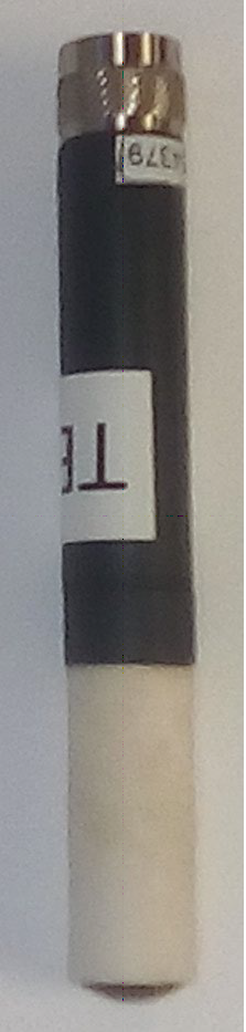
Figure 207
Rotronics (HC2A-S) RH/T Probe
•The Rotronics (HC2A-S) RH/T Sensor/Probe’s plug is inserted into the socket on the bottom of the Transmitter and its retaining collar tightened. See Figure 208 below:
Figure 208
| Note: | Though the Rotronic HC2A-S sensor/probe is typically mounted on the case via a socket, it can be remotely mounting via the Y527 (2 metre) or Y528 (5 metre) extension cables. |
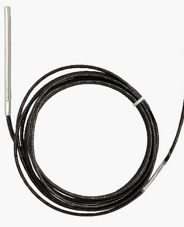
Figure 209
•The PT1000 probe (J182) Sensor/Probe is connected to the Transmitter Unit as outlined HERE.
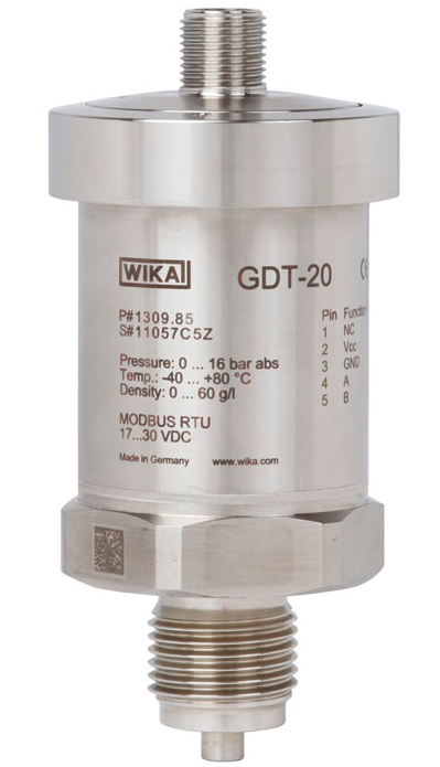
Figure 210
WIKA Model GDT-20 Sensor/Probe
•The WIKA Model GDT 20 Sensor/Probe is connected to the Transmitter Unit as outlined HERE.
•The are 4 cable glands in total, three for the Sensor/Probe(s) cables and 1 cable gland for the external power supply. This Transmitter/Sensor Unit cannot be battery powered.
•Compatible Sensor/Probes are connected to the Transmitter Unit as outlined HERE.
Figure 211 |
Figure 212 |
Figure 213
|
|
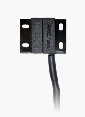
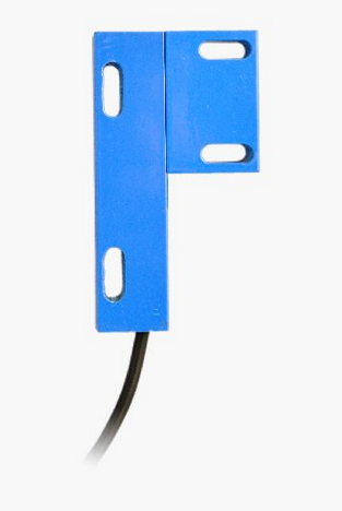
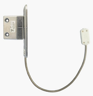
•Door Sensor(s)/Probe(s) are connected to the Transmitter Unit as outlined HERE.