Navigation:
Installation, Configuration and Operation of Hardware > Installation and Configuration of Additional Devices > Hanwell SMS Module >> Hanwell IceSpy SMS Module Installation and Operation
Hanwell IceSpy SMS Module Installation and Operation

Contents
SIM Installation
| Note 1: | Make sure that both SMS Sending and Receiving is enabled by your cellular Service provider for the SIM card you are using. |
| Note 2: | Refer to PIN Verification below. |
| Caution: | The SIM card is not hot-swappable, DO NOT attempt to remove the SIM card without first disconnecting the power and removing the battery. It is recommended that the battery be removed, when the SMS Module is not in use. |
The SIM card must be installed prior to battery installation and wall mounting as follows:
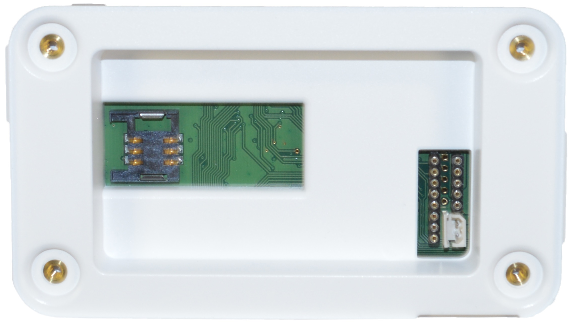
1.Remove the battery cover and slide the SIM card into the exposed SIM socket, so that the gold plated contacts on the SIM card connect with the gold plated contacts of the SIM socket. See Figure 223 below:
Figure 223
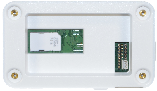
2.Once the SIM is correctly located in the socket, fit the battery and battery cover and mount the SMS module; see Physical Installation Procedure (typical) for details. See Figure 224 below:
Figure 224
LED Operation
The SMS Module has three LEDs which provide a quick visual indication of current status.
|
The red SMS Cross LED will be off during normal operation. •It will flash slowly during a power failure. |
|
The amber SMS tick LED will be on during normal operation. •It will flash approximately twice a second if there is no network connection to the EMS Server. |
|
The green power LED will illuminate during normal operation. •It will go off during a power failure. |
Push Button
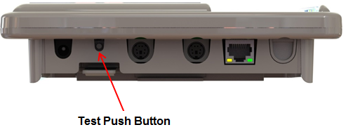
Briefly press the Test Push Button, located on the lower left of the SMS Unit's bottom panel. See Figure 225 below:
Figure 225
The SIM status and Signal Strength (RSSI) is displayed on the Unit's screen. See Figure 226 below:
Figure 226
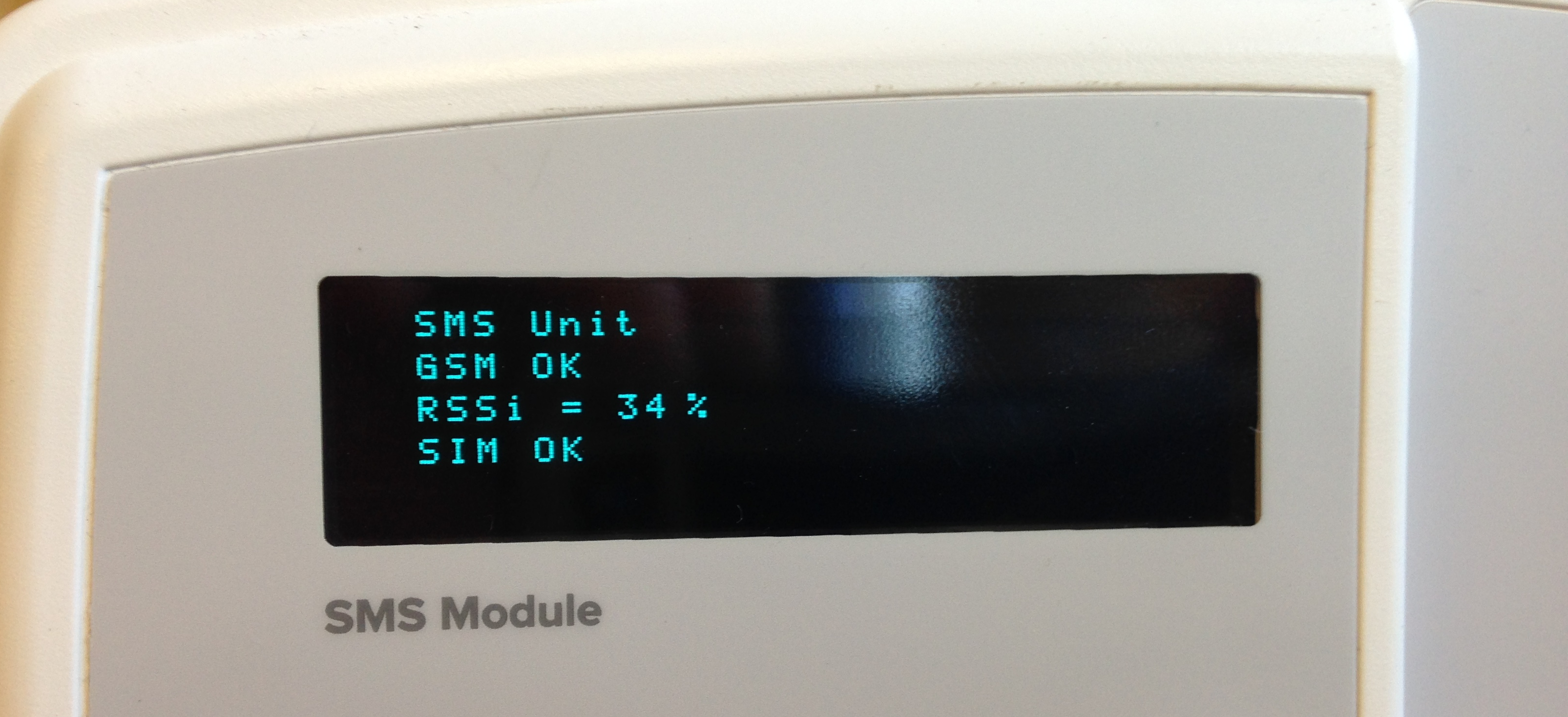
Press and hold the Test Push Button for at least five seconds to send a test message to one of the SMS Power & Comm's Group phone numbers. The SMS Module will display the phone number at the bottom of the OLED display, when the message is sent.
•When the relay is on due to an Alarm, a brief press of the Test Push Button will reset the Alarm Relay.
If the Unit's Display (See Figure 226 above) shows SIM: No and GPRS: No, the SIM card may have PIN Verification enabled, which cannot be used with the SMS Unit.
•If this is the case:
i.Disconnect the SMS Unit from its power supply and remove its batteries.
ii.Remove the SIM card from the Unit.
iii.Insert the SIM into a mobile phone using the same type of SIM.
iv.Use the mobile phone's functionality to disable PIN Verification.
v.Remove the SIM from the mobile phone and insert it back into the SMS Unit.
vi.Replace the Unit's batteries and reconnect its power supply.
Error Message
When initially powering on the Unit, pressing the Test push button will display the message:
"Unit not fully powered up. Wait 60 seconds and try again."
If pressing the Test push button continues to display the message above after a few minutes, then there may be a problem with your SIM or cellular phone account.