•Sensor Transmitter Units
•Data Logger Units
•Gain and Offset Linear
➢Gain and Offset Calculation
•Connecting 4000 Series Linear Sensor-Transmitter/Data Logger Units to External Probes
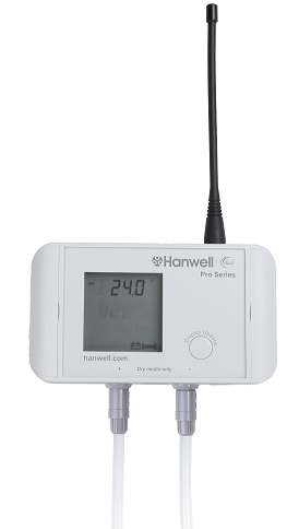
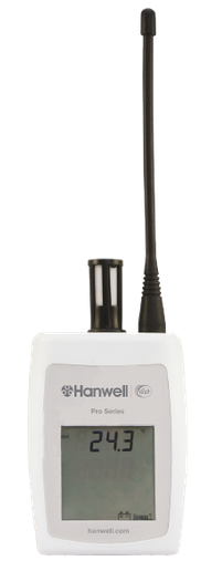
•Hanwell Pro Sensor-Transmitters/Data Loggers
➢HL4000 Hanwell Pro Sensors - Data Loggers
➢RL4000 Hanwell Pro Sensors -Transmitters
➢RL8000 8 Channel Datanet+ Module
➢ML4000 Hanwell Pro Sensors -Transmitters and Data Loggers
❖Important: See note regarding LUX/UV Sensors-Transmitters and Digital Alarms
➢Hanwell 4000 Series Durable Transmitter-Sensors/Data Loggers
•Hanwell Pro Sensor-Transmitters/Data Loggers - Spare Parts and Accesories
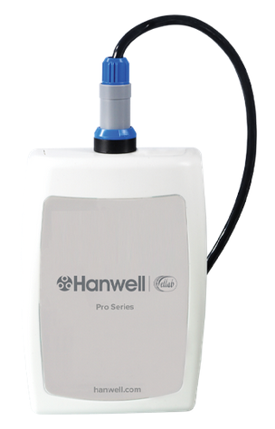
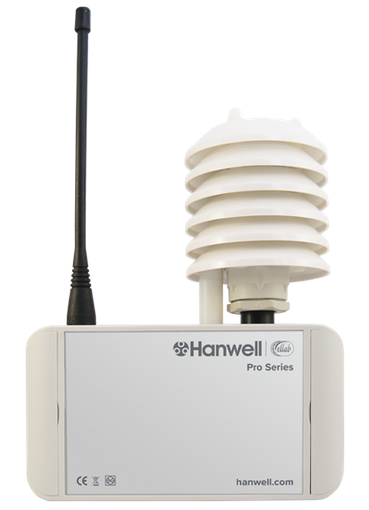
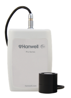
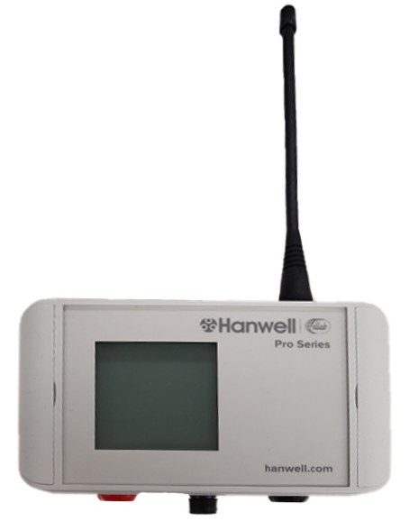
Sensor-Transmitter Units
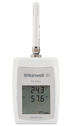
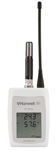
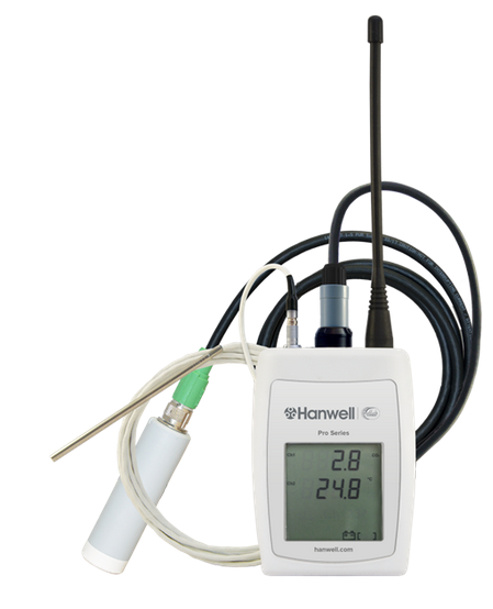
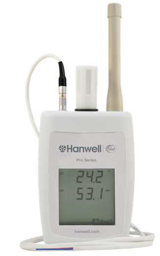
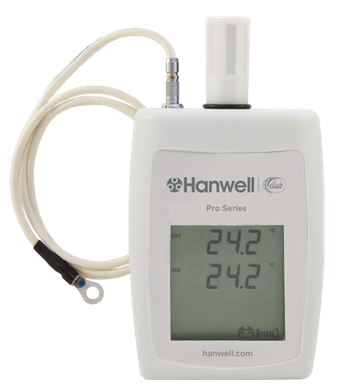
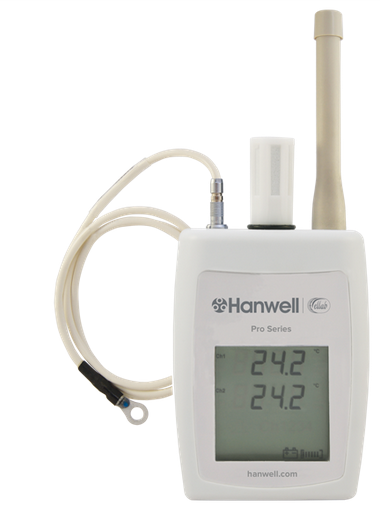
The Hanwell Pro 4000 Series Sensor-Transmitter Units are, essentially, transmitters with one, two or three data channels. The Units take data received from attached sensors/probes and transmit it to the Hanwell EMS System at defined Transmission Intervals, either directly or via an SR2 Controller.
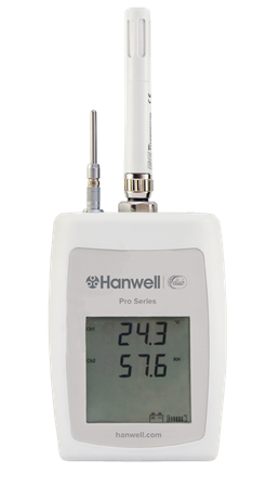
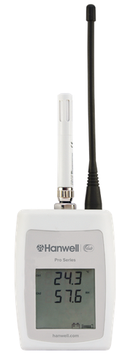
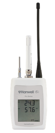
•The Sensor Units' probe(s) themselves can be mounted directly onto the 4000 Series Sensor-Transmitter Unit’s case or on a lead(s) connected to the Unit.
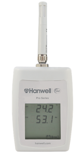
•The current Data Values, battery voltage/predicted battery life and (optionally) the Alarm Status are displayed on the Sensor-Transmitter Units’ LCD screens.
•The Sensor-Transmitter Units are configured with the EMS software via a USB connection.
•The Sensor-Transmitter Units hold their Calibration Data in their on-board memory and can also be programmed with the High/Low Alarm Values set on the EMS host PC/Server.
•Mark 8 and above 4000 Series Sensor-Transmitter Units can also log data on-board in their internal memory.
You may find it useful to refer to Document IM5990 - 4000 Series Sensor Units User Guide.
Part Code
|
Sensor Type
|
Transmitter
|
Transmitter Logs
|
Logger
|
EMS/Synergy Compatibility
|
4001
|
Single Thermistor
|
Yes
|
Yes
|
Yes
|
All versions
|
4002
|
Dual Thermistor
|
Yes
|
Yes
|
Yes
|
All versions
|
4007
|
Single Thermistor
|
Yes
|
Yes
|
Yes
|
All versions
|
4012
|
Thermistor + Door
|
Yes
|
Yes*
|
No
|
All versions
|
4106
|
Thermistor, Sensirion, %Relative Humidity (RH)
|
Yes
|
Yes
|
Yes
|
All versions
|
4107
|
Thermistor, Sensirion, Flood
|
Yes
|
Yes**
|
No
|
All versions
|
4108
|
Thermistor, Sensirion, ext Thermistor
|
Yes
|
Yes
|
Yes
|
All versions
|
4109
|
Relative Humidity (RH) and Temperature
|
Yes
|
Yes
|
Yes
|
All versions
|
4111
|
Rotronics Temperature and %Relative Humidity (RH) -40°C to +60°C
|
Yes
|
Yes
|
Yes
|
All versions
|
4112
|
Rotronics Temperature and %Relative Humidity (RH) -50oC to 100oC
|
Yes
|
Yes
|
Yes
|
EMS >= 1.0.11/2.0.4
|
4114
|
EE07 Temperature and %Relative Humidity (RH)
|
Yes
|
Yes
|
Yes
|
All versions
|
4115
|
Thermistor, EE07 %Relative Humidity (RH)
|
Yes
|
Yes
|
Yes
|
All versions
|
4116
|
EE07 Temperature and %Relative Humidity (RH), Thermistor
|
Yes
|
Yes
|
Yes
|
All versions
|
4301
|
Single PT100 3 wire (-200oC to +110oC)
|
Yes
|
Yes
|
Yes
|
All versions
|
4302
|
Dual PT100 3 wire (-200oC to +110oC)
|
Yes
|
Yes
|
Yes
|
All versions
|
4401
|
Single PT100 4 wire (-200oC to +110oC)
|
Yes
|
Yes
|
Yes
|
All versions
|
4402
|
Dual PT100 4 wire (-200oC to +110oC)
|
Yes
|
Yes
|
Yes
|
All versions
|
4403
|
Single PT100 4 wire (-100oC to +250oC)
|
Yes
|
Yes
|
Yes
|
All versions
|
4404
|
Dual PT100 4 wire (-100oC to +250oC)
|
Yes
|
Yes
|
Yes
|
All versions
|
4410
|
Single PT100 + Door (-200oC to +110oC)
|
Yes
|
Yes*
|
No
|
EMS >= 1.0.11/2.0.4
|
4411
|
Single PT100 4 wire (-200oC to +160oC)
|
Yes
|
Yes
|
Yes
|
All versions
|
4412
|
Dual PT100 4 wire (-200oC to +160oC)
|
Yes
|
Yes
|
Yes
|
All versions
|
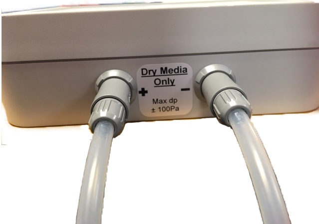
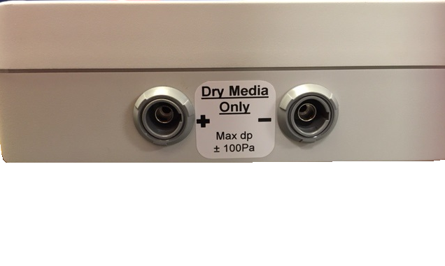
4502
|
Differential Pressure ±1250PA
|
Yes
|
Yes
|
Yes
|
All versions
|
4509
|
Differential Pressure ±50PA
|
Yes
|
Yes
|
Yes
|
All versions
|
4512
|
Thermistor, CO2
|
Yes
|
Yes
|
Yes
|
EMS and Synergy >= 1.7.3/2.2.0
|
4601
|
Current Clamp
|
Yes
|
Yes
|
No
|
EMS and Synergy >= 1.7.3
|
4602
|
Outdoor Current Clamp
|
Yes
|
Yes
|
Yes
|
All versions
|
4604
|
Single Channel Pulse Counter
|
Yes
|
No
|
No
|
All versions
|
4701
|
LUX
Important:
See note regarding LUX/UV Sensors-Transmitters and Digital Alarms
|
Yes
|
Yes
|
Yes
|
All versions
|
4702
|
LUX
Important:
See note regarding LUX/UV Sensors-Transmitters and Digital Alarms
|
Yes
|
Yes
|
Yes
|
All versions
|
4703
|
LUX and UV
Important:
See note regarding LUX/UV Sensors-Transmitters and Digital Alarms
|
Yes
|
Yes
|
Yes
|
All versions
|
4704
|
LUX and UV
Important:
See note regarding LUX/UV Sensors-Transmitters and Digital Alarms
|
Yes
|
Yes
|
Yes
|
All versions
|
4803
|
Single Channel Digital Sensor
|
Yes
|
No
|
No
|
All versions
|
4804
|
Radio Dual Channel Digital Sensor
|
Yes
|
No
|
No
|
All versions
|
4805
|
Flood Digital
|
Yes
|
No
|
No
|
All versions
|
4806
|
Flood Digital, Digital
|
Yes
|
No
|
No
|
All versions
|
4809
|
Dual 4 - 20 mA
|
Yes
|
Yes
|
No
|
All versions
|
4810
|
Single 0 - 5 Volt
|
Yes
|
Yes
|
No
|
All versions
|
4901
|
Single Thermocouple (-200oC to +200oC)
|
Yes
|
Yes
|
Yes
|
EMS >= 1.0.8/2.0.2
|
4902
|
Single Thermocouple (-200oC to 200oC) + door
|
Yes
|
Yes*
|
No
|
EMS >= 1.0.8/2.0.2
|
4903
|
Single Thermocouple (-50oC to +350oC)
|
Yes
|
Yes
|
Yes
|
EMS >= 1.0.8/2.0.2
|
4904
|
Single Thermocouple (-50oC to +350oC) + door
|
Yes
|
Yes*
|
No
|
EMS >= 1.0.8/2.0.2
|
Durable Units (DU) - Enhanced IP Rating
|
Part Code
|
Sensor Type
|
Transmitter
|
Transmitter Logs
|
Logger
|
EMS Compatibility
|
RL4509-DU
|
Differential Pressure ±50PA
|
Yes
|
Yes
|
Yes
|
All versions
|
RL4402-DU
|
Dual PT100 4 wire (-200oC to +110oC)
Note: Employs Hanwell IceSpy Probes
|
Yes
|
Yes
|
Yes
|
All Versions
|
RL4413-DU
|
Relative Humidity (RH), Temperature (-20oC to +60oC), LUX (Digital)
|
Yes
|
Yes
|
Yes
|
All Versions
|
ML4109-DU
|
Relative Humidity (RH) and Temperature (-20oC to +60oC)
|
Yes
|
Yes
|
Yes
|
All Versions
|
Notes:
|
*Door Status is only recorded on internal logging at the pre-set logging interval. Door Status is transmitted on status change
**Only Relative Humidity (RH) and Temperature are recorded on internal logging, not Flood.
|
|
Data Logger Units
The Hanwell Pro 4000 Series Data Logger Units collect data from from attached sensors/probes on one, two or three data channels and save it to their memory. The collected data can then be downloaded to the Hanwell EMS System via a USB connection/cable.
•The Data Loggers' probe(s) themselves can be mounted directly onto the 4000 Series Data Loggers' case or on a lead(s) connected to the Unit.
•The current Data Values, battery voltage/predicted battery life are displayed on the Data Loggers' LCD screens.
•The Data Logger Units are configured with the EMS software via a USB connection.
•The Data Logger Units hold their Calibration Data in their on-board memory.
Gain and Offset Linear
Gain and Offset Calculation for Hanwell Pro Sensor-Transmitters/Data Loggers
| Note: | If you require the IceSpy Linear Calculator, please CLICK HERE. |
| Caution: | DO NOT use the Linear Calculator for RL8000 Linear inputs, use the calibration values supplied with the System |
When required, both Offset and Gain can be calculated from the Manufacturer’s specifications, for the Sensor you wish to use, by using the Calculator below:
Hanwell Pro Sensor-Transmitter/Data Logger Linear Gain and Offset Calculator
|
To use the Gain and Offset Calculator:
1.Select the Hanwell Pro transmitter type, from the Hanwell Type drop down list.
2.Enter the Minimum and Maximum voltage or current output from your sensor into the Sensor Output Type fields.
3.Enter the Upper and Lower limits of your sensor's measurement range into the Sensor Output Range fields.
Example:
You are using a sensor that measures CO2 from 0 to 10000 ppm and outputs 4 to 20mA with a Hanwell Pro 4 to 20mA transmitter.
1.Select 4 to 20mA as the Hanwell Type.
2.Enter 4 'to' 20 into the Sensor Output Type fields.
3.Enter 0 'to' 10000 into the Sensor Output Range fields.
4.Then click Calculate to get the required Gain and Offset; in this case the values will be 3.052503 and 819.
5.Enter the values calculated by the above table into the Calibration pane, accessed from EMS's Edit Mode.
•These values are then sent to the Device when it is Synchronised with the EMS Database.
•For further information on Gain and Offset calculation, please refer to Document: TS6066 - Calibrating Linear Sensors.
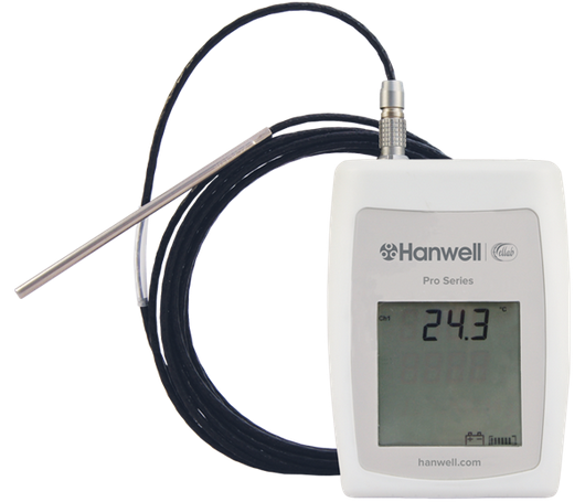
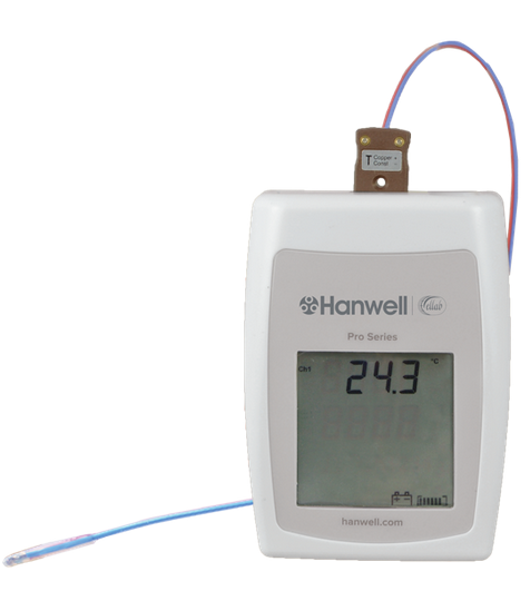
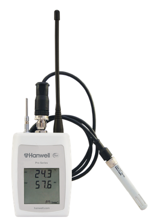
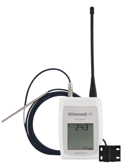
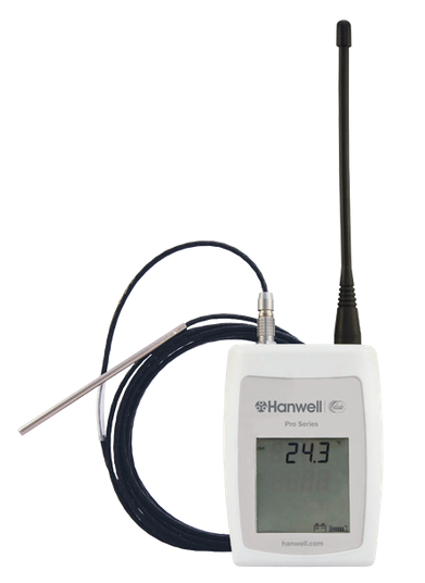
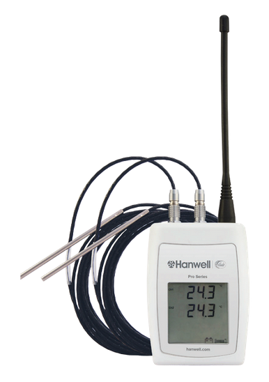
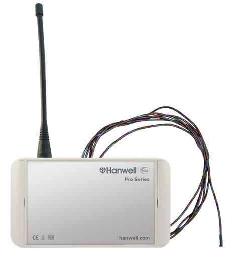
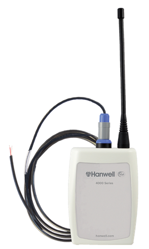
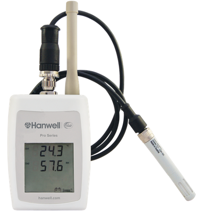
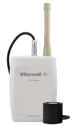
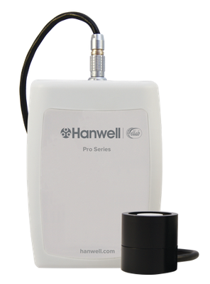
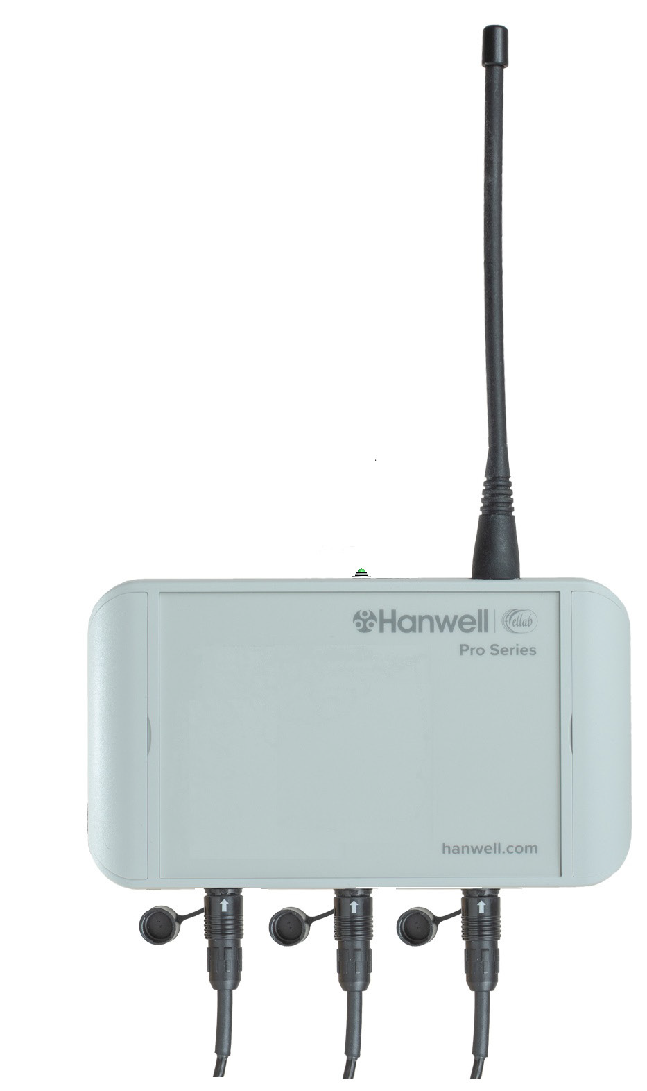
Connecting 4000 Series Linear Sensor-Transmitter/Data Logger Units to External Probes
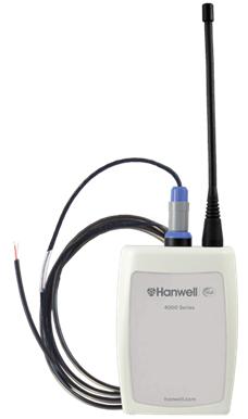
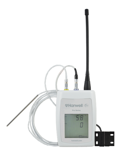
Figure 193
Sensor-Transmitter Units supplied with wiring for external probes (see example in 193 above) should be connected to them as follows:
Channel No.
|
+ve
|
-ve
|
1
|
Green
|
Black
|
2
|
Red
|
White
|
3
|
Yellow
|
Blue
|
| Note: | Any unused pairs of wires should be twisted together. |
Hanwell Pro Sensor-Transmitters/Data Loggers
HL4000 Hanwell Pro Sensors - Data Loggers
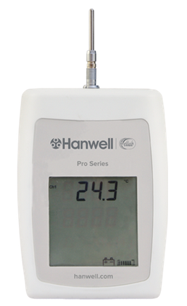
HL4001 and HL4002 Temperature Data Logger -40°C to +60°C
Part Code
|
Sensor Type
|
Transmitter
|
Transmitter Logs
|
Logger
|
EMS/Synergy Compatibility
|
Add to EMS/Synergy as:
|
4001
|
Single Thermistor
|
Yes
|
Yes
|
Yes
|
All Versions
|
Thermistor
|
4002
|
Dual Thermistor
|
Yes
|
Yes
|
Yes
|
All Versions
|
Dual Termistor
|
➢Part of the Hanwell Pro HL4000T Series. ➢The HL4001 (Single Channel) and HL4002 (Dual Channel) Temperature Data Loggers include an LCD display. ➢Temperature Measurement Range: -40°C to +60°C ➢Probes are available separately. ➢Datasheet |
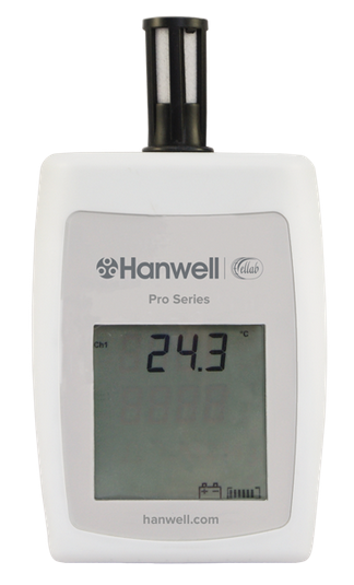
HL4007 - Temperature Data Logger -20°C to +60°C
Part Code
|
Sensor Type
|
Transmitter
|
Transmitter Logs
|
Logger
|
EMS/Synergy Compatibility
|
Add to EMS/Synergy as:
|
4007
|
Single Thermistor
|
Yes
|
Yes
|
Yes
|
All Versions
|
Thermistor
|
➢Part of the Hanwell Pro HL4000T Series. ➢The HL4007 Data Logger is a Single Channel Data Logger for temperature measurement with LCD display and internal temperature sensor. ➢Temperature Measurement Range: -20°C to +60°C. ➢Datasheet |
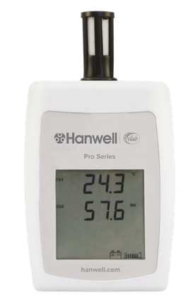
HL4106 Temperature and Humidity Data Logger -20°C to +60°C and 10 to 90%RH non-condensing
Part Code
|
Sensor Type
|
Transmitter
|
Transmitter Logs
|
Logger
|
EMS/Synergy Compatibility
|
Add to EMS/Synergy as:
|
4106
|
Thermistor, Sensirion, % Relative Humidity (RH)
|
Yes
|
Yes
|
Yes
|
All Versions
|
Thermistor/RH
|
➢Part of the Hanwell Pro HL4000RHT Series. ➢The HL4106 Data Logger is a combined Temperature and Humidity unit fitted with on-board sensors. ➢Temperature Measurement Range: -20°C to +60°C. ➢Humidity Measurement Range: 10 to 90%RH non-condensing. ➢Datasheet |
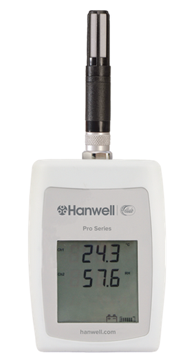
HL4111 Temperature and Humidity Data Logger -50°C to +100°C and 0 - 100% RH
Part Code
|
Sensor Type
|
Transmitter
|
Transmitter Logs
|
Logger
|
EMS/Synergy Compatibility
|
Add to EMS/Synergy as:
|
4111
|
Rotronics Temp and % Relative Humidity (RH)
|
Yes
|
Yes
|
Yes
|
All Versions
|
Thermistor R/H
|
➢Part of the Hanwell Pro HL4000RHT Series. ➢The HL4111 RH/T Data Logger measures a Single Channel using a highly accurate RH/T probe. ➢Temperature Measurement Range: -50°C to +100°C ➢Humidity Measurement Range: 0 - 100% RH ➢Probes are available separately ➢Datasheet |
HL4114 Temperature and Humidity Data Logger
Part Code
|
Sensor Type
|
Transmitter
|
Transmitter Logs
|
Logger
|
EMS/Synergy Compatibility
|
Add to EMS/Synergy as:
|
4114
|
EE07 Temperature and % Relative Humidity (RH)
|
Yes
|
Yes
|
Yes
|
All Versions
|
Thermistor/RH
|
➢Part of the Hanwell Pro HL4000RHT Series. ➢The HL4114 RH/T Data Logger measures a Single Channel using a highly accurate RH/T probe. ➢Temperature Measurement Range: -40°C to +80°C with external probe ➢Probes are available separately. ➢Datasheet |
HL4115 RH/T and Thermistor Data Logger
Part Code
|
Sensor Type
|
Transmitter
|
Transmitter Logs
|
Logger
|
EMS/Synergy Compatibility
|
Add to EMS/Synergy as:
|
4115
|
Thermistor, EE07 % Relative Humidity (RH)
|
Yes
|
Yes
|
Yes
|
All Versions
|
Thermistor/RH
|
➢Part of the HL4000RHT Series. ➢The HL4115 RH/T Data Logger has an LCD display and two channels for external Temperature and RH Sensors. ➢Temperature Measurement Range: -40°C to +60°C ➢Humidity Measurement Range: 0 - 100%RH non-condensing with external probes. ➢Probes are available separately. ➢Datasheet |
HL4401 and HL4402 High Temperature Data Loggers
Part Code
|
Sensor Type
|
Transmitter
|
Transmitter Logs
|
Logger
|
EMS/Synergy Compatibility
|
Add to EMS/Synergy as:
|
4401
|
Single PT100 4 wire (-200oC to +110oC)
|
Yes
|
Yes
|
Yes
|
All Versions
|
PT100
|
4402
|
Dual PT100 4 wire (-200oC to +110oC)
|
Yes
|
Yes
|
Yes
|
All Versions
|
Dual PT100
|
➢Part of the Hanwell Pro HL4000T Series. ➢The HL4401 (Single Channel) and HL4402 (Dual Channel) high-temperature Data Loggers are compatible with 4-wire PT100 probes and fitted with 5-pin metal Lemo sockets and LCD displays. ➢Temperature Measurement Range: -200°C to +110°C ➢Probes are available separately. ➢Datasheet |
HL4512 CO2 Data Logger
Part Code
|
Sensor Type
|
Transmitter
|
Transmitter Logs
|
Logger
|
EMS/Synergy Compatability
|
Add to EMS/Synergy as:
|
4512
|
Thermistor, CO2
|
Yes
|
Yes
|
Yes
|
EMS
Synergy >= 1.7.3/2.2.0
|
CO2/Thermistor
|
IMPORTANT
Customers with Synergy Versions 2.2.0 and 2.3.0
Please contact Hanwell Technical Support for help before buying and ask them for the:
V2.2.0 and V2.3.0 Sensor List Upgrade for RL4512 patch
|
➢Part of the Hanwell Pro HL4000T Series. ➢The HL4512 measures and logs CO2 and temperature using highly accurate external sensors. The instrument includes LCD display. ➢Temperature Measurement Range: -40°C to +60oC ➢Datasheet |
HL4601 Energy Data Loggers
Part Code
|
Sensor Type
|
Transmitter
|
Transmitter Logs
|
Logger
|
EMS/Synergy Compatibility
|
4601
|
Current Clamp
|
Yes
|
Yes
|
No
|
EMS and Synergy 1.7.3
|
IMPORTANT
Synergy Customers and Customers with EMS prior to Version 1.0.10
Please contact Hanwell Technical Support for help before buying and ask them to check RIK for: RL4601 Current Clamp Compatibility.
|
➢Part of the Hanwell Pro Utility Range. ➢The HL4601 Series of Energy Data Loggers measure the output of Current Clamps providing fast and reliable information about energy usage and cost. Note: We recommend that you contact us to discuss your application for these products before purchase.
➢Datasheet |
HL4602 Outdoor Energy Data Logger
Part Code
|
Sensor Type
|
Transmitter
|
Transmitter Logs
|
Logger
|
EMS/Synergy Compatibility
|
4602
|
Outdoor Current Clamp
|
Yes
|
Yes
|
Yes
|
All Versions
|
➢Part of the Hanwell Pro Utility Range. ➢The HL4602 Outdoor Energy Data Logger is designed for use with specific Current Clamps to provide Energy Usage information. ➢Datasheet |
HL4901 Temperature Data Logger -200oC to +200oC and HL4903 Temperature Data Logger -50oC to +350oC
Part Code
|
Sensor Type
|
Transmitter
|
Transmitter Logs
|
Logger
|
EMS/Synergy Compatibility
|
Add to EMS/Synergy as:
|
4901
|
Single Thermocouple (-200oC to 200oC)
|
Yes
|
Yes
|
Yes
|
EMS > = 1.0.8/2.0.2
|
Thermocouple (-200,200)
|
4903
|
Single Thermocouple (-50oC to +350oC)
|
Yes
|
Yes
|
Yes
|
EMS > = 1.0.8/2.0.2
|
Thermocouple (-50,350)
|
IMPORTANT
Customers with EMS Version 1.0.8
Please contact Hanwell Technical Support for help before buying and ask them for the:
Management Tools DP and Digital Patch for EMS patch
|
➢Part of the Hanwell Pro HL4900 Series. ➢The HL4901 and HL4903 are Thermocouple Data Loggers which include an LCD and a large data memory. ➢Probes are available separately. ➢Datasheet |
|
RL4000 Hanwell Pro Sensors -Transmitters
RL4001 and RL4002 Temperature Transmitter -40°C to +60°C
Part Code
|
Sensor Type
|
Transmitter
|
Transmitter Logs
|
Logger
|
EMS/Synergy Compatibility
|
Add to EMS/Synergy as:
|
4001
|
Single Thermistor
|
Yes
|
Yes
|
Yes
|
All Versions
|
Thermistor
|
4002
|
Dual Thermistor
|
Yes
|
Yes
|
Yes
|
All Versions
|
Dual Thermistor
|
➢Part of the RL4000T Series. ➢The RL4001 (Single Channel) and RL4002 (Dual Channel) wireless data logger includes an LCD display and operates on the 434.075MHz frequency. ➢Temperature Measurement Range: -40°C to +60°C ➢Probes are available separately. ➢Datasheet |
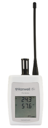
RL4007 Wireless Temperature and Humidity Logger -20°C to +60°C
Part Code
|
Sensor Type
|
Transmitter
|
Transmitter Logs
|
Logger
|
EMS/Synergy Compatibility
|
Add to EMS/Synergy as:
|
4007
|
Single Thermistor
|
Yes
|
Yes
|
Yes
|
All Versions
|
Thermistor
|
➢Product Code: RL4007-434.075 ➢Part of the RL4000T Series. ➢The RL4007 is a Single Channel Temperature Transmitter with LCD display and an internal Temperature Sensor. ➢As standard, it operates on the 434.075MHz frequency, but other frequencies are available upon request. ➢Temperature Measurement Range: -20°C to +60°C. ➢Datasheet |
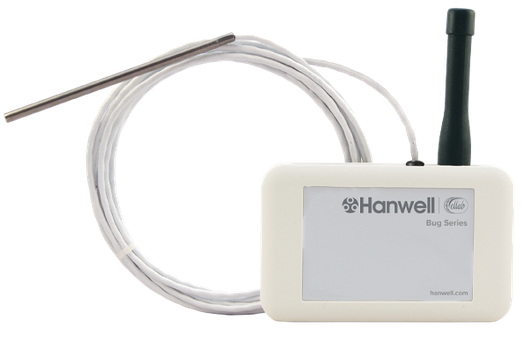
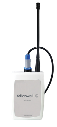
RL401 Slimline Radio Transmitter with External Temperature Sensor
➢Product Code: RL401-434.075 ➢Part of the Hanwell Pro 400 (Bug) Series ➢The RL401 is a slimline Single Channel Thermistor Unit with an External Temperature Probe ➢The RL401 has no display. ➢Temperature Measurement Range: -40°C to +55°C ➢Add to EMS/Synergy as: Thermistor ➢Datasheet |
|
RL4012 Temperature Transmitter with Door Switch -40°C to +60°C
Part Code
|
Sensor Type
|
Transmitter
|
Transmitter Logs
|
Logger
|
EMS/Synergy Compatibility
|
Add to EMS/Synergy as:
|
4012
|
Thermistor + Door
|
Yes
|
Yes*
|
No
|
All Versions
|
Thermistor Digital
|
*Door Status is only recorded on internal logging at the pre-set logging interval. Door Status is transmitted on Status Change.
➢Product Code: RL4012-434.075 ➢Part of the RL4000T Series ➢The RL4012 (Dual Channel) Transmitter provides Temperature measurement and is fitted with a door switch, LCD display and 2 Pin Lemo socket. ➢Temperature Measurement Range: -20°C to +60°C which is extended to -40°C to +100°C with external probes ➢Probes are available separately. ➢Datasheet |
RL407 Slimline Wireless Temperature Logger
➢Product Code: RL407-434.075 ➢Part of the Hanwell Pro 400 (Bug) Series ➢The RL407 is a slimline Single Channel Thermistor Unit with fitted with an internal temperature sensor. ➢The RL407 has no display. ➢Temperature Measurement Range: -10°C to +55°C ➢Add to EMS/Synergy as: Thermistor ➢Datasheet |
RL410 Slimline Radio Transmitter with Fixed External Temperature Sensor
➢Product Code: RL410-434.075 ➢Part of the Hanwell Pro 400 (Bug) Series ➢The RL410 is a slimline Single Channel wireless Temperature Data Logger Unit fitted with an External Temperature sensor. ➢The RL410 Unit has no display. ➢Temperature Measurement Range: -40°C to +55°C ➢Add to EMS/Synergy as: Thermistor ➢Datasheet |
RL4106 Temperature and Humidity Radio Transmitter
Part Code
|
Sensor Type
|
Transmitter
|
Transmitter Logs
|
Logger
|
EMS/Synergy Compatibility
|
Add to EMS/Synergy as:
|
4106
|
Thermistor, Sensirion, % Relative Humidity (RH)
|
Yes
|
Yes
|
Yes
|
All Versions
|
Thermistor/RH
|
➢Product Code: RL4106-434.075 ➢Part of the RL4000RHT Series ➢The RL4106 is a Combined Temperature and Humidity Radio Transmitter with internal sensors. ➢Temperature Measurement Range: -20°C to +60°C ➢Humidity Measurement Range: 10 to 90% RH non condensing. ➢Datasheet |
RL4107 RH/T and Water Leak Radio Transmitter
Part Code
|
Sensor Type
|
Transmitter
|
Transmitter Logs
|
Logger
|
EMS/Synergy Compatibility
|
Add to EMS/Synergy as:
|
4107
|
Thermistor, Sensirion, Flood
|
Yes
|
Yes**
|
No
|
All Versions
|
Thermistor/RH
|
➢Product Code: RL4107-434.075 ➢Part of the Hanwell Pro RL4000RHT Series. ➢The RL4107 Radio Transmitter is fitted with onboard Temperature and Humidity sensors and has the option of connecting a Leak Detection Cable. ➢Temperature Measurement Range: -20°C to +60°C ➢Humidity Measurement Range: 10 to 90%RH ➢Datasheet |
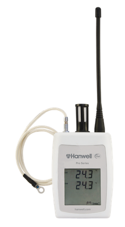
RL4108 RH/T and Surface Temperature Radio Transmitter
Part Code
|
Sensor Type
|
Transmitter
|
Transmitter Logs
|
Logger
|
EMS/Synergy Compatibility
|
Add to EMS/Synergy as:
|
4108
|
Thermistor, Sensirion, External Thermistor
|
Yes
|
Yes
|
Yes
|
All Versions
|
Thermistor/RH/Thermistor
|
➢Product Code: RL4108-434.075 ➢Part of the Hanwell Pro RL4000RHT Series. ➢The RL4108 RH/T Radio Transmitter is fitted with onboard sensors and an, optional, Remote Surface Temperature probe. ➢Temperature Measurement Range: -20°C to +60°C which is extended to 0°C to +125°C with external probes. ➢Humidity Measurement Range: 10 to 90% RH non-condensing. ➢External Probes are available separately. ➢Datasheet |
RL4111 Temperature and Humidity Transmitter -40°C to +60°C
Part Code
|
Sensor Type
|
Transmitter
|
Transmitter Logs
|
Logger
|
EMS/Synergy Compatibility
|
Add to EMS/Synergy as:
|
4111
|
Rotronics Temp and % Relative Humidity (RH)
-40°C to +60°C
|
Yes
|
Yes
|
Yes
|
All Versions
|
Thermistor/RH
|
➢Product Code: RL4111-434.075 ➢Part of the Hanwell Pro RL4000RHT Series. ➢The RL4111 RH/T Radio Transmitter uses a highly accurate RH/T probe. ➢Temperature Measurement Range: -40°C to +60°C ➢Humidity Measurement Range: 0 to100% RH ➢Probes are available separately. ➢Datasheet |
RL4112 Temperature and Humidity Radio Transmitter -50°C to +100°C
Part Code
|
Sensor Type
|
Transmitter
|
Transmitter Logs
|
Logger
|
EMS/Synergy Compatibility
|
Add to EMS/Synergy as:
|
4112
|
Rotronics Temp and % Relative Humidity (RH)
-50°C to +100°C
|
Yes
|
Yes
|
Yes
|
EMS >= 1.0.11/2.0.4
|
Linear/RH
|
➢Product Code: RL4112-434.075 ➢Part of the Hanwell Pro RL4000RHT Series. ➢The RL4112 RH/T Radio Transmitter uses a highly accurate RH/T probe. ➢Temperature Measurement Range: -50°C to +100°C ➢Humidity Measurement Range: 0 to100% RH ➢Probes are available separately. ➢Datasheet |
RL4114 Temperature and Humidity Radio Transmitter
Part Code
|
Sensor Type
|
Transmitter
|
Transmitter Logs
|
Logger
|
EMS/Synergy Compatibility
|
Add to EMS/Synergy as:
|
4114
|
EE07 Temperature and % Relative Humidity (RH)
|
Yes
|
Yes
|
Yes
|
All Versions
|
Thermistor/RH
|
➢Product Code: RL4114-434.075 ➢Part of the Hanwell Pro RL4000RHT Series. ➢The RL4114 RH/T Radio Transmitter uses a highly accurate RH/T probe. ➢Temperature Measurement Range: -40°C to +80°C with external probe. ➢Probes are available separately. ➢Datasheet |
RL4115 RH/T and Thermistor Radio Transmitter
Part Code
|
Sensor Type
|
Transmitter
|
Transmitter Logs
|
Logger
|
EMS/Synergy Compatibility
|
Add to EMS/Synergy as:
|
4115
|
Thermistor, EE07 % Relative Humidity (RH)
|
Yes
|
Yes
|
Yes
|
All Versions
|
Thermistor/RH
|
➢Product Code: RL4115-434.075 ➢Part of the Hanwell Pro RL4000RHT Series. ➢The RL4115 RH/T Radio Transmitter has C-Sense Temperature and EE07-02 RH Probe compatibility. ➢Temperature Measurement Range: -40°C to +60°C ➢Humidity Measurement Range: 0 to 100% RH non-condensing with external probes ➢Probes are available separately. ➢Datasheet |
RL4116 RH/T and Thermistor Radio Transmitter
Part Code
|
Sensor Type
|
Transmitter
|
Transmitter Logs
|
Logger
|
EMS/Synergy Compatibility
|
Add to EMS/Synergy as:
|
4116
|
Thermistor, EE07 Temperature and % Relative Humidity (RH)
|
Yes
|
Yes
|
Yes
|
All Versions
|
Thermistor/RH/Thermistor
|
➢Product Code: RL4116-434.075 ➢Part of the Hanwell Pro RL4000RHT Series. ➢The RL4116 RH/T Radio Transmitter has C-Sense Temperature and RH probes. ➢Temperature Measurement Range: -40°C to +80°C ➢Humidity Measurement Range: 0 to 100%RH non-condensing with external probes. ➢Probes are available separately. ➢Datasheet |
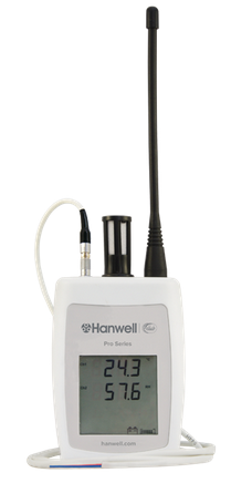
RL4401 and RL4402 Temperature Transmitter -200oC to +110oC

Part Code
|
Sensor Type
|
Transmitter
|
Transmitter Logs
|
Logger
|
EMS/Synergy Compatibility
|
Add to EMS/Synergy as:
|
4401
|
Single PT100 4 wire (-200oC to +110oC)
|
Yes
|
Yes
|
Yes
|
All Versions
|
PT100
|
4402
|
Dual PT100 4 wire (-200oC to +110oC)
|
Yes
|
Yes
|
Yes
|
All Versions
|
Dual PT100
|
➢Part of the RL4000T Series. ➢The RL4401 (single channel) and RL4402 (dual channel) is a 4-wire PT100 unit fitted with a 5-pin metal Lemo socket for the external temperature sensor and an LCD display. ➢Temperature Measurement Range: -200°C to +110°C ➢Probes are available separately. ➢Datasheet |
RL4410 PT100 Transmitter -200°C to +110°C
Part Code
|
Sensor Type
|
Transmitter
|
Transmitter Logs
|
Logger
|
EMS/Synergy Compatibility
|
Add to EMS/Synergy as:
|
4410
|
Single PT100 + Door (-200oC to +110oC)
|
Yes
|
Yes*
|
No
|
EMS >= 1.0.11/2.0.4
|
PT100/Digital
|
Important Note:
As this device is a composite of existing Chanel types, it is possible to add it to Synergy 1.7.3 and earlier versions of EMS by updating sensordefs.xml in either application and clicking Sensor Models in the config utility.
Please contact Hanwell Support for advice on this before buying.
|
*Door Status is only recorded on internal logging at the pre-set logging interval. Door Status is transmitted on Status Change.
➢Product Code: RL4410-434.075 ➢Part of the RL4000T Series, the RL4410 PT100 transmitter is for use with a light duty door switch and a PT100 sensor, LCD display and 434.075MHz frequency as standard. ➢Instrument measuring range: -200°C to +110°C ➢Probes are available separately ➢Datasheet |
RL4411 PT100 Transmitter -200°C to +160°C
Part Code
|
Sensor Type
|
Transmitter
|
Transmitter Logs
|
Logger
|
EMS/Synergy Compatibility
|
Add to EMS/Synergy as:
|
4411
|
Single PT100 (-200oC to +160oC)
|
Yes
|
Yes
|
Yes
|
All Versions
|
PT100
|
Important Note:
Unit must be Synchronised to work.
|
➢Product Code: RL4411-434.075-1 ➢Part of the RL4000T Series, the RL4411 is a temperature transmitter for 4 wire PT100 sensors, 5 pin Lemo socket and includes LCD display and 434.075MHz frequency as standard. ➢Instrument measuring range: -200°C to +160°C ➢Probes are available separately ➢Datasheet |
RL4412 Dual PT100 Transmitter -200°C to +160°C
Part Code
|
Sensor Type
|
Transmitter
|
Transmitter Logs
|
Logger
|
EMS/Synergy Compatibility
|
Add to EMS/Synergy as:
|
4412
|
Dual PT100 (-200oC to +160oC)
|
Yes
|
Yes
|
Yes
|
All Versions
|
Dual PT100
|
Important Note:
Unit must be Synchronised to work.
|
➢Product Code: RL4412-434.075-1-1 ➢Part of the RL4000T Series, the RL4412 is a dual channel temperature transmitter for 4 wire PT100 sensors, 5 pin Lemo socket and includes LCD display and 434.075MHz frequency as standard. ➢Instrument measuring range: -200°C to +160°C ➢Probes are available separately ➢Datasheet |
RL4502 and RL4509 Differential Pressure Radio Transmitter
Part Code
|
Sensor Type
|
Transmitter
|
Transmitter Logs
|
Logger
|
EMS/Synergy Compatibility
|
Add to EMS/Synergy as:
|
4502
|
DP ±1250PA
|
Yes
|
Yes
|
Yes
|
All Versions
|
Differential Pressure
|
4509
|
DP ±50PA
|
Yes
|
Yes
|
Yes
|
All Versions
|
Differential Pressure
|
IMPORTANT
Customers with EMS Version 1.0.8
Please contact Hanwell Technical Support for help before buying and ask them for the:
Management Tools DP and Digital Patch for EMS patch
|
➢Product Code: RL4502-9 ➢The RL4502 (no display) and RL4509 (LCD display) Differential Pressure Transmitter units are fitted with a variety of differential pressure sensors. ➢Datasheet |
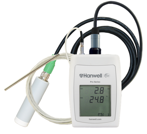
RL4512 CO2 and Temperature Transmitter
Part Code
|
Sensor Type
|
Transmitter
|
Transmitter - Logger
|
Logger
|
EMS/Synergy Compatibility
|
Add to EMS/Synergy as:
|
4512
|
Thermistor, CO2
|
Yes
|
Yes
|
Yes
|
EMS
Synergy > = 1.7.3/2.2.0
|
CO2/Thermistor
|
IMPORTANT
Customers with Synergy Versions 2.2.0 and 2.3.0
Please contact Hanwell Technical Support for help before buying and ask them for the:
V2.2.0 and V2.3.0 Sensor List Upgrade for RL4512 patch
|
➢Product Code: RL4512-434.075 ➢The RL4512 is an externally powered CO2 and Thermistor sensor with an internal battery to be used for setting up and downloading data from the unit. ➢The CO2 is Channel 1 and Thermistor is Channel 2. ➢Datasheet ➢For further information, please refer to Document: IM5984 - RL4512 Dual Channel CO2 and Temperature Sensor Unit - User Guide.
|
RL4601 Energy Transmitter
Part Code
|
Sensor Type
|
Transmitter
|
Transmitter - Logger
|
Logger
|
EMS/Synergy Compatibility
|
Add to EMS/Synergy as:
|
4601
|
Current Clamp
|
Yes
|
Yes
|
No
|
EMS
Synergy 1.7.3
|
Triple Current Clamp
|
IMPORTANT
Synergy Customers and Customers with EMS prior to Version 1.0.10
Please contact Hanwell Technical Support for help before buying and ask them to check RIK for: RL4601 Current Clamp Compatibility.
|
➢Part of the Hanwell Pro Utility Range. ➢The RL4601 range of transmitters can be used with a variety of current clamps. ➢See Technical Specification for information on the appropriate Current Clamp to be used. ➢Datasheet ➢For further information please refer to Document: IM6015 4000 Series Current Clamp Devices - Instruction Manual
|
RL4602 Outdoor Energy Radio Transmitters
Part Code
|
Sensor Type
|
Transmitter
|
Transmitter - Logger
|
Logger
|
EMS/Synergy Compatibility
|
Add to EMS/Synergy as:
|
4602
|
Outdoor Current Clamp
|
Yes
|
Yes
|
Yes
|
All Versions
|
Triple Current Clamps
|
➢Product Code: RL4602 ➢Part of the Hanwell Pro Utility Range. ➢The RL4602 Outdoor Radio Transmitters are designed for use with specific current clamps to provide Energy Usage information. ➢See Technical Specification for information on the appropriate Current Clamp to be used. ➢Datasheet |
RL4604 Radio Transmitter – Single Channel Pulse Counter
Part Code
|
Sensor Type
|
Transmitter
|
Transmitter - Logger
|
Logger
|
EMS/Synergy Compatibility
|
Add to EMS/Synergy as:
|
4604
|
Single Channel Pulse Counter
|
Yes
|
No
|
No
|
All Versions
|
Pulse Counter
|
➢Product Code: RL4604-434.075 ➢Part of the Hanwell Pro Utility range. ➢The RL4604 Radio Transmitter is a Single Channel Pulse Counter used to collect data from electricity water and gas meter outputs. ➢Datasheet |
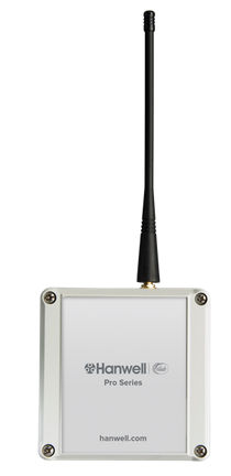
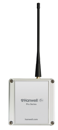
RL4803 and RL4804 Radio Transmitter
Part Code
|
Sensor Type
|
Transmitter
|
Transmitter - Logger
|
Logger
|
EMS/Synergy Compatibility
|
Add to EMS/Synergy as:
|
4803
|
Single Channel Digital Sensor
|
Yes
|
No
|
No
|
All Versions
|
Single Digital
|
IMPORTANT
RL4803 Transmitter-Sensors are compatible with: RadioLog 8, EMS 1.0.10 or later and EMS 2.0.3 or later.
To operate with earlier versions of EMS or Synergy, add the Units as Dual Digital
|
4804
|
Radio Dual Channel Digital Sensor
|
Yes
|
No
|
No
|
All Versions
|
Dual Digital
|
➢Part of the RL4800 Series. ➢The RL4803 (Single Channel) and RL4804 (Dual Channel) are Digital Radio Transmitter Units for use internally or externally. ➢Each unit includes a steel bracket for mounting purposes. ➢Datasheet RL4803 and RL4804 Relay Connection Schematic
| Note: | Ensure that the relay used is suitable for this application, eg. if fitted with a Snubber, the capacitance is 10nF or less and the contacts are Volt free. |
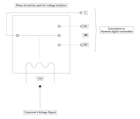
| Warning: | There will be an overall delay of up to 2 minutes from transmitting a State Change to a reaction being generated in the application.
Furthermore, if using SMS, there may be a further delay through external third party phone providers. |
|
RL4805 and RL4806 Flood Transmitter
Part Code
|
Sensor Type
|
Transmitter
|
Transmitter - Logger
|
Logger
|
EMS/Synergy Compatibility
|
Add to EMS/Synergy as:
|
4805
|
Flood Digital
|
Yes
|
No
|
No
|
All Versions
|
Single Digital
|
IMPORTANT
RL4805 Transmitter-Sensors are compatible with: RadioLog 8, EMS 1.0.10 or later and EMS 2.0.3 or later.
To operate with earlier versions of EMS or Synergy, add the Units as Dual Digital
|
|
4806
|
Flood Digital, Digital
|
Yes
|
No
|
No
|
All Versions
|
Dual Digital
|
➢Part of the Flood Series ➢The RL4805 and RL4806 Single and Dual Channel Transmitters are Flood Sensors, used for flood detection. ➢Flood cable supplied separately (By the meter). ➢Datasheet |
RL4809 4-20mA Transmitter
Part Code
|
Sensor Type
|
Transmitter
|
Transmitter - Logger
|
Logger
|
EMS/Synergy Compatibility
|
Add to EMS/Synergy as:
|
4809
|
Dual 4 - 20mA
|
Yes
|
Yes
|
No
|
All Versions
|
Dual Linear
|
➢Product Code: RL4809-434.075 ➢Part of the Flood Series. ➢The RL4809 is a Dual Channel Transmitter with 2 x 4 to 20mA inputs for use internally or externally. ➢Each unit includes a steel bracket for mounting purposes. ➢Datasheet Using the RL4809 Sensor-Transmitter
You will need a Y055 USB lead to synchronise this device with either Synergy or RadioLog. Please consult the relevant manual for details on adding and configuring sensors. It should be added as a Dual Linear sensor.
•By default, the device will show mA directly. If you wish to display Engineering units other than mA, then the Offset, Gain, Channel Title, Display Units and Precision can be changed as required.
•The Offset - The raw value which will correspond to 0 in the units you are using. •The Gain - The change in actual value per raw count. Both of the above can be calculated from the manufacturer’s specifications for the 4 to 20mA sensor you wish to use.
•To help you with this please visit: the Linear Gain and Offset Calculator. •The theory behind Gain and Offset calculation is explained at: http://pd.hanwell.com/TS6066 Calibrating Linear Sensors.pdf Enter the calculated values by editing the sensor properties on the PC and then sending any changes to the device using the Calibrate function.
|
RL4810 Air Flow Radio Transmitter
Part Code
|
Sensor Type
|
Transmitter
|
Transmitter - Logger
|
Logger
|
EMS/Synergy Compatibility
|
Add to EMS/Synergy as:
|
4810
|
Single 0 - 5volt
|
Yes
|
Yes
|
No
|
All Versions
|
Dual Linear
|
➢Product Code: RL4810-434.075 ➢The RL4810 Radio Transmitter is designed specifically for air flow measurement and is to be used with the high accuracy air flow sensors specified in the Technical Specification. ➢Air Flow ranges: 0-5m/s, 0-10m/s, 0-20m/s (Probes sold separately). ➢Datasheet |
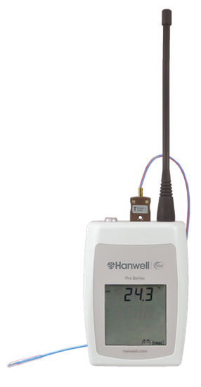
RL4901 Temperature Transmitter
Part Code
|
Sensor Type
|
Transmitter
|
Transmitter - Logger
|
Logger
|
EMS/Synergy Compatibility
|
Add to EMS/Synery as:
|
4901
|
Single Thermocouple (-200oC to +200oC)
|
Yes
|
Yes
|
Yes
|
EMS > = 1.0.8/2.0.2
|
Thermocouple(-200,200)
|
IMPORTANT
Customers with EMS Version 1.0.8
Please contact Hanwell Technical Support for help before buying and ask them for the:
Management Tools DP and Digital Patch for EMS patch
|
* Door status is only recorded on internal logging at pre-set logging interval. Door Status is transmitted on status change.
➢Part of the Hanwell Pro RL4900 Series. ➢The RL4901 Unit is a Thermocouple Wireless Data Logger which includes an LCD display and operates on the 434.075MHz frequency as standard. ➢Temperature Range: -200°C to +200°C ➢Probes are available separately. ➢Datasheet |
RL4902 Temperature Transmitter
Part Code
|
Sensor Type
|
Transmitter
|
Transmitter - Logger
|
Logger
|
EMS/Synergy Compatibility
|
Add to EMS/Synery as:
|
4902
|
Single Thermocouple (-200oC to +200oC) + Door
|
Yes
|
Yes*
|
No
|
EMS > = 1.0.8/2.0.2
|
Thermocouple(-200,200)/Digital
|
IMPORTANT
Customers with EMS Version 1.0.8
Please contact Hanwell Technical Support for help before buying and ask them for the:
Management Tools DP and Digital Patch for EMS patch
|
* Door status is only recorded on internal logging at pre-set logging interval. Door Status is transmitted on status change.
➢Part of the Hanwell Pro RL4900 Series. ➢The RL4902 Unit is a Thermocouple Wireless Data Logger which includes an LCD display and operates on the 434.075MHz frequency as standard. ➢Temperature Range: -200°C to +200°C ➢Probes are available separately. ➢Datasheet |
RL4903 Temperature Transmitter
Part Code
|
Sensor Type
|
Transmitter
|
Transmitter - Logger
|
Logger
|
EMS/Synergy Compatibility
|
Add to EMS/Synery as:
|
4903
|
Single Thermocouple (-50oC to +350oC)
|
Yes
|
Yes
|
Yes
|
EMS > = 1.0.8/2.0.2
|
Thermocouple(-50,350)
|
IMPORTANT
Customers with EMS Version 1.0.8
Please contact Hanwell Technical Support for help before buying and ask them for the:
Management Tools DP and Digital Patch for EMS patch
|
* Door status is only recorded on internal logging at pre-set logging interval. Door Status is transmitted on status change.
➢Part of the Hanwell Pro RL4900 Series. ➢The RL4903 Unit is a Thermocouple Wireless Data Logger which includes an LCD display and operates on the 434.075MHz frequency as standard. ➢Temperature Range: -50°C to +350°C ➢Probes are available separately. ➢Datasheet |
RL4904 Temperature Transmitter
Part Code
|
Sensor Type
|
Transmitter
|
Transmitter - Logger
|
Logger
|
EMS/Synergy Compatibility
|
Add to EMS/Synery as:
|
4904
|
Single Thermocouple (-50oC to +350oC) + Door
|
Yes
|
Yes*
|
No
|
EMS > = 1.0.8/2.0.2
|
Thermocouple(-50,350)/Digital
|
IMPORTANT
Customers with EMS Version 1.0.8
Please contact Hanwell Technical Support for help before buying and ask them for the:
Management Tools DP and Digital Patch for EMS patch
|
* Door status is only recorded on internal logging at pre-set logging interval. Door Status is transmitted on status change.
➢Part of the Hanwell Pro RL4900 Series. ➢The RL4904 Unit is a Thermocouple Wireless Data Logger which includes an LCD display and operates on the 434.075MHz frequency as standard. ➢Temperature Range: -50°C to +350°C ➢Probes are available separately. ➢Datasheet |
|
RL8000 8 Channel Datanet+ Module
Each RL8000 (a locally powered 8-channel module) offers inputs that can be individually configured to directly support a wide range of industry standard sensor types.
For information on the Datanet+ System and the RL8000 Unit it is built around, please refer to IM6142 RL8000/DATANET+ Module User Guide.
| Caution: | DO NOT use the Linear Calculator for RL8000 Linear inputs, use the calibration values supplied with the System |
|
ML4000 Hanwell Pro Sensors -Transmitters and Data Loggers
ML4106 Temperature and Humidity Data Logger
Part Code
|
Sensor Type
|
Transmitter
|
Transmitter Logs
|
Logger
|
EMS/Synergy Compatibility
|
Add to EMS/Synergy as:
|
4106
|
Thermistor, Sensirion, % Relative Humidity (RH)
|
Yes
|
Yes
|
Yes
|
All Versions
|
Thermistor/RH
|
➢The ML4106 Data Logger monitors Temperature and Humidity with an onboard RH/T Sensor. ➢Temperature Measurement Range: -20°C to +60°C ➢Humidity Measurement Range: 0 - 100%RH ➢Datasheet |
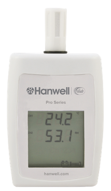
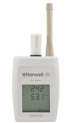
ML4106 Wireless Temperature and Humidity Transmitter
Part Code
|
Sensor Type
|
Transmitter
|
Transmitter Logs
|
Logger
|
EMS/Synergy Compatibility
|
Add to EMS/Synergy as:
|
4106
|
Thermistor, Sensirion, % Relative Humidity (RH)
|
Yes
|
Yes
|
Yes
|
All Versions
|
Thermistor/RH
|
➢Part of the Hanwell Pro ML4000RHT Series. ➢The ML4106 RH/T Radio Transmitter is fitted with onboard Temperature and Humidity Sensors. ➢Temperature Measurement Range: -20°C to +60°C ➢Humidity Measurement Range: 0 - 100%RH non-condensing. ➢Datasheet. |
ML4107 Temperature, Humidity and Water Leak Transmitter
Part Code
|
Sensor Type
|
Tranmitter
|
Transmitter Logs
|
Logger
|
EMS/Synergy Compatibility
|
Add to EMS/Synergy as:
|
4107
|
Thermistor, Sensirion, Flood
|
Yes
|
Yes**
|
No
|
All Versions
|
Thermistor/RH
|
**Only Relative Humidity and Temperature are recorded on internal logging, not Flood.
➢Part of the Hanwell Pro ML4000RHT Series. ➢The ML4107 RH/T Radio Transmitter is fitted with onboard RH/T sensors and is compatible with an optional additional flood probe. ➢Temperature Measurement Range: -20°C to +60°C ➢Humidity Measurement Range: 10 - 90% RH ➢Datasheet |
ML4108 RH/T and Surface Temperature Data Logger
Part Code
|
Sensor Type
|
Transmitter
|
Transmitter Logs
|
Logger
|
EMS/Synergy Compatibility
|
Add to EMS/Synergy as:
|
4108
|
Thermistor, Sensirion, External Thermistor
|
Yes
|
Yes
|
Yes
|
All Versions
|
Thermistor/RH/Thermistor
|
➢The ML4108 Data Logger is a three channel Temperature and Humidity Logger with optional Remote Surface Temperature Probe. ➢Temperature Measurement Range: -20°C to +60°C which is extended to 0°C to +125°C with external probes. ➢Humidity Measurement Range: 10 - 90%RH non-condensing. ➢External Probes are available separately. ➢Datasheet |
ML4108 RH/T and External Thermistor Radio Transmitter
Part Code
|
Sensor Type
|
Transmitter
|
Transmitter Logs
|
Logger
|
EMS/Synergy Compatibility
|
Add to EMS/Synergy as:
|
4108
|
Thermistor, Sensirion, External Thermistor
|
Yes
|
Yes
|
Yes
|
All Versions
|
Thermistor/RH/Thermistor
|
➢Part of the Hanwell Pro ML4000RHT Series. ➢The ML4108 RH/T Radio Transmitter has an onboard RH/T sensor and optional Remote Surface Temperature Probe. ➢Temperature Measurement Range: -20°C to +60°C which is extended to 0°C to +125°C with external probes. ➢Humidity Measurement Range: 10 - 90% RH non-condensing. ➢External Probes are available separately. ➢Datasheet |
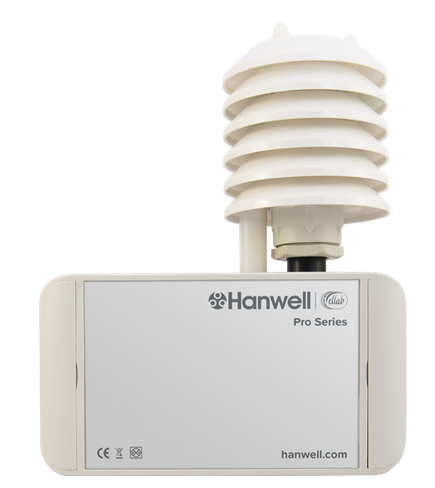
ML4109 Temperature and Humidity Outdoor Data Logger
Part Code
|
Sensor Type
|
Transmitter
|
Transmitter Logs
|
Logger
|
EMS/Synergy Compatibility
|
Add to EMS/Synergy as:
|
4109
|
Relative Humidity (RH) & Temperature
|
Yes
|
Yes
|
Yes
|
All Versions
|
Thermistor/RH
|
➢Product Code: ML4109-OD ➢The ML4109 Data Logger monitors Temperature and Humidity and is suitable for outdoor use. ➢Temperature Measurement Ranges between -40°C to +60°C. ➢Datasheet |
ML4109 RH/T Outdoor Radio Transmitter
Part Code
|
Sensor Type
|
Transmitter
|
Transmitter Logs
|
Logger
|
EMS/Synergy Compatibility
|
Add to EMS/Synergy as:
|
4109
|
Relative Humidity (RH) & Temperature
|
Yes
|
Yes
|
Yes
|
All Versions
|
Thermistor/RH
|
➢Product Code: ML4109-OD-434.075 ➢Part of the Hanwell Pro ML4000RHT Series. ➢The ML4109 Outdoor RH/T Radio Transmitter provides a high degree of accuracy using an EE07 probe. ➢Temperature Measurement Range: -40°C to +60°C ➢Datasheet |
ML4114 RH/T Data Logger
Part Code
|
Sensor Type
|
Transmitter
|
Transmitter Logs
|
Logger
|
EMS/Synergy Compatibility
|
Add to EMS/Synergy as:
|
4114
|
EE07 Temperature and % Relative Humidity (RH)
|
Yes
|
Yes
|
Yes
|
All Versions
|
Thermistor/RH
|
➢Product Code: ML4114 ➢Part of the Hanwell Pro ML4000RHT Series. ➢The ML4114 Temperature and Humidity Data Logger measures a single channel using a highly accurate RH/T probe. ➢Temperature Measurement Range: -40°C to +80°C with external probe ➢Probes are available separately. ➢Datasheet |
ML4114 Temperature and Humidity Radio Transmitter
Part Code
|
Sensor Type
|
Transmitter
|
Transmitter Logs
|
Logger
|
EMS/Synergy Compatibility
|
Add to EMS/Synergy as:
|
4114
|
EE07 Temperature and % Relative Humidity (RH)
|
Yes
|
Yes
|
Yes
|
All Versions
|
Thermistor/RH
|
➢Product Code: ML4114-434.075 ➢Part of the Hanwell Pro ML4000RHT Series. ➢The ML4114 is a highly accurate Temperature and Humidity Radio Transmitter typically used within the heritage industry. It has an additional temperature channel. ➢Temperature Measurement Range: -40°C to +80°C with external probe ➢Probes are available separately. ➢Datasheet |
ML4701 LUX Data Logger (LuxBug)
Part Code
|
Sensor Type
|
Transmitter
|
Transmitter Logs
|
Logger
|
EMS/Synergy Compatibility
|
Add to EMS/Synergy as:
|
4701
|
Lux
|
Yes
|
Yes
|
Yes
|
All Versions
|
LUX/UV
|
➢Product Code: ML4701 ➢Part of the Hanwell Pro ML4000LUX/UV Series. ➢The Hanwell Pro ML4701 LUX Data Logger (previously known as LuxBug) has an onboard LUX Sensor. ➢Visible Light Measurement Range: 10 to 5000 LUX ➢Datasheet ➢Definitions of LUX and Cumulative LUX
Lux
LUX is a measure of the brightness of the incident light but measured in such a way as to be comparable with the subjective opinion formed by the human eye.
In practise this means choosing a detector that has a similar spectral response to our own eye. Hanwell Instruments use a photocell which gives an accuracy of approximately 1% FSD.
•The Lux is the SI Unit of Illuminance, measuring Luminous Flux per unit area. •One Lux is defined as a brightness corresponding to one Lumen per square meter. Where:
•Illuminance is a measure of how much Luminous Flux is spread over a given area; that is, a measure of the intensity of illumination on a surface •Luminous Flux (measured in Lumens) is a measure of the total ‘amount’ of visible light present. And:
•The Lumen is the SI Unit of Luminous Flux, a measure of the total quantity of visible light emitted by a source per unit of time. | Note: | Luminous Flux differs from ‘power', i.e. Radiant Flux in that Radiant Flux includes all electro-magnetic waves emitted, while Luminous Flux is weighted according to a model/Luminosity Function of the human eye's sensitivity to various wavelengths of electro-magnetic radiation. |
Therefore, to be clear, the Lumen is a measure of the total quantity of visible light emitted by a source weighted so it is as would be seen by the standard human eye.
Cumulative Lux
Damage from light is cumulative in its effect; that is, the longer you leave an item exposed to light, the more damage the exposure will cause.
Reducing the damage done by light means considering both intensity of the light (Lux) and the length of exposure.
| For Example: | A delicate watercolourcolorexposed to 50 Lux for 100 hours will experience the same damage as if it were exposed to 100 Lux for 50 hours. |
•Prior to EMS Version 1.0.10 ( 2.0.3 EMS Compliant) Cumulative Lux is expressed as the sum of all Lux readings. •From EMS Version 1.0.10 (2.0.3 EMS Compliant) onwards, Cumulative Lux is expressed as Lux/Hours over the elected period. |
|
ML4701 LUX Radio Transmitter (LuxBug)
Part Code
|
Sensor Type
|
Transmitter
|
Transmitter Logs
|
Logger
|
EMS/Synergy Compatibility
|
4702
|
Lux
|
Yes
|
Yes
|
Yes
|
All Versions
|
➢Product Code: ML4702-434.075 ➢Part of the Hanwell Pro ML4000LUX/UV Series. ➢The ML4702 LUX transmitter is fitted with an onboard LUX sensor. ➢Datasheet ➢Definitions of LUX and Cumulative LUX
Lux
LUX is a measure of the brightness of the incident light but measured in such a way as to be comparable with the subjective opinion formed by the human eye.
In practise this means choosing a detector that has a similar spectral response to our own eye. Hanwell Instruments use a photocell which gives an accuracy of approximately 1% FSD.
•The Lux is the SI Unit of Illuminance, measuring Luminous Flux per unit area. •One Lux is defined as a brightness corresponding to one Lumen per square meter. Where:
•Illuminance is a measure of how much Luminous Flux is spread over a given area; that is, a measure of the intensity of illumination on a surface •Luminous Flux (measured in Lumens) is a measure of the total ‘amount’ of visible light present. And:
•The Lumen is the SI Unit of Luminous Flux, a measure of the total quantity of visible light emitted by a source per unit of time. | Note: | Luminous Flux differs from ‘power', i.e. Radiant Flux in that Radiant Flux includes all electro-magnetic waves emitted, while Luminous Flux is weighted according to a model/Luminosity Function of the human eye's sensitivity to various wavelengths of electro-magnetic radiation. |
Therefore, to be clear, the Lumen is a measure of the total quantity of visible light emitted by a source weighted so it is as would be seen by the standard human eye.
Cumulative Lux
Damage from light is cumulative in its effect; that is, the longer you leave an item exposed to light, the more damage the exposure will cause.
Reducing the damage done by light means considering both intensity of the light (Lux) and the length of exposure.
| For Example: | A delicate watercolourcolorexposed to 50 Lux for 100 hours will experience the same damage as if it were exposed to 100 Lux for 50 hours. |
•Prior to EMS Version 1.0.10 ( 2.0.3 EMS Compliant) Cumulative Lux is expressed as the sum of all Lux readings. •From EMS Version 1.0.10 (2.0.3 EMS Compliant) onwards, Cumulative Lux is expressed as Lux/Hours over the elected period. |
|
ML4702 LUX Data Logger
Part Code
|
Sensor Type
|
Transmitter
|
Transmitter Logs
|
Logger
|
EMS/Synergy Compatibility
|
4702
|
Lux
|
Yes
|
Yes
|
Yes
|
All Versions
|
➢Product Code: ML4702 ➢Part of the Hanwell Pro ML4000LUX/UV Series. ➢The ML4702 LUX Data Logger is fitted with onboard sensors and discreet design. ➢Visible Light Measurement Range: 10 to 5000 LUX ➢Datasheet ➢Definitions of LUX and Cumulative LUX
Lux
LUX is a measure of the brightness of the incident light but measured in such a way as to be comparable with the subjective opinion formed by the human eye.
In practise this means choosing a detector that has a similar spectral response to our own eye. Hanwell Instruments use a photocell which gives an accuracy of approximately 1% FSD.
•The Lux is the SI Unit of Illuminance, measuring Luminous Flux per unit area. •One Lux is defined as a brightness corresponding to one Lumen per square meter. Where:
•Illuminance is a measure of how much Luminous Flux is spread over a given area; that is, a measure of the intensity of illumination on a surface •Luminous Flux (measured in Lumens) is a measure of the total ‘amount’ of visible light present. And:
•The Lumen is the SI Unit of Luminous Flux, a measure of the total quantity of visible light emitted by a source per unit of time. | Note: | Luminous Flux differs from ‘power', i.e. Radiant Flux in that Radiant Flux includes all electro-magnetic waves emitted, while Luminous Flux is weighted according to a model/Luminosity Function of the human eye's sensitivity to various wavelengths of electro-magnetic radiation. |
Therefore, to be clear, the Lumen is a measure of the total quantity of visible light emitted by a source weighted so it is as would be seen by the standard human eye.
Cumulative Lux
Damage from light is cumulative in its effect; that is, the longer you leave an item exposed to light, the more damage the exposure will cause.
Reducing the damage done by light means considering both intensity of the light (Lux) and the length of exposure.
| For Example: | A delicate watercolourcolorexposed to 50 Lux for 100 hours will experience the same damage as if it were exposed to 100 Lux for 50 hours. |
•Prior to EMS Version 1.0.10 ( 2.0.3 EMS Compliant) Cumulative Lux is expressed as the sum of all Lux readings. •From EMS Version 1.0.10 (2.0.3 EMS Compliant) onwards, Cumulative Lux is expressed as Lux/Hours over the elected period. |
|
ML4703 LUX and UV Data Logger
Part Code
|
Sensor Type
|
Transmitter
|
Transmitter Logs
|
Logger
|
EMS/Synergy Compatibility
|
Add to EMS/Synergy as:
|
4703
|
Lux & UV
|
Yes
|
Yes
|
Yes
|
All Versions
|
LUX/UV
|
➢Product Code: ML4703 ➢Part of the Hanwell Pro ML4000LUX/UV Series. ➢The ML4703 LUX and UV Data Logger is fitted with an onboard LUX and UV sensors. ➢Visible Light Measurement Range: 10 to 5000 LUX ➢UV Power Measurement Range: 20 to 2000 mW/m2 ➢Datasheet ➢Definitions of LUX and Cumulative LUX
Lux
LUX is a measure of the brightness of the incident light but measured in such a way as to be comparable with the subjective opinion formed by the human eye.
In practise this means choosing a detector that has a similar spectral response to our own eye. Hanwell Instruments use a photocell which gives an accuracy of approximately 1% FSD.
•The Lux is the SI Unit of Illuminance, measuring Luminous Flux per unit area. •One Lux is defined as a brightness corresponding to one Lumen per square meter. Where:
•Illuminance is a measure of how much Luminous Flux is spread over a given area; that is, a measure of the intensity of illumination on a surface •Luminous Flux (measured in Lumens) is a measure of the total ‘amount’ of visible light present. And:
•The Lumen is the SI Unit of Luminous Flux, a measure of the total quantity of visible light emitted by a source per unit of time. | Note: | Luminous Flux differs from ‘power', i.e. Radiant Flux in that Radiant Flux includes all electro-magnetic waves emitted, while Luminous Flux is weighted according to a model/Luminosity Function of the human eye's sensitivity to various wavelengths of electro-magnetic radiation. |
Therefore, to be clear, the Lumen is a measure of the total quantity of visible light emitted by a source weighted so it is as would be seen by the standard human eye.
Cumulative Lux
Damage from light is cumulative in its effect; that is, the longer you leave an item exposed to light, the more damage the exposure will cause.
Reducing the damage done by light means considering both intensity of the light (Lux) and the length of exposure.
| For Example: | A delicate watercolourcolorexposed to 50 Lux for 100 hours will experience the same damage as if it were exposed to 100 Lux for 50 hours. |
•Prior to EMS Version 1.0.10 ( 2.0.3 EMS Compliant) Cumulative Lux is expressed as the sum of all Lux readings. •From EMS Version 1.0.10 (2.0.3 EMS Compliant) onwards, Cumulative Lux is expressed as Lux/Hours over the elected period. |
|
ML4703 LUX and UV Transmitter
Part Code
|
Sensor Type
|
Transmitter
|
Transmitter Logs
|
Logger
|
EMS/Synergy Compatibility
|
Add to EMS/Synergy as:
|
4703
|
Lux & UV
|
Yes
|
Yes
|
Yes
|
All Versions
|
LUX/UV
|
➢Product Code: ML4703-434.075 ➢Part of the Hanwell Pro ML4000LUX/UV Series. ➢The ML4703 LUX and UV Transmitter is fitted with onboard sensors. ➢Datasheet ➢Definitions of LUX and Cumulative LUX
Lux
LUX is a measure of the brightness of the incident light but measured in such a way as to be comparable with the subjective opinion formed by the human eye.
In practise this means choosing a detector that has a similar spectral response to our own eye. Hanwell Instruments use a photocell which gives an accuracy of approximately 1% FSD.
•The Lux is the SI Unit of Illuminance, measuring Luminous Flux per unit area. •One Lux is defined as a brightness corresponding to one Lumen per square meter. Where:
•Illuminance is a measure of how much Luminous Flux is spread over a given area; that is, a measure of the intensity of illumination on a surface •Luminous Flux (measured in Lumens) is a measure of the total ‘amount’ of visible light present. And:
•The Lumen is the SI Unit of Luminous Flux, a measure of the total quantity of visible light emitted by a source per unit of time. | Note: | Luminous Flux differs from ‘power', i.e. Radiant Flux in that Radiant Flux includes all electro-magnetic waves emitted, while Luminous Flux is weighted according to a model/Luminosity Function of the human eye's sensitivity to various wavelengths of electro-magnetic radiation. |
Therefore, to be clear, the Lumen is a measure of the total quantity of visible light emitted by a source weighted so it is as would be seen by the standard human eye.
Cumulative Lux
Damage from light is cumulative in its effect; that is, the longer you leave an item exposed to light, the more damage the exposure will cause.
Reducing the damage done by light means considering both intensity of the light (Lux) and the length of exposure.
| For Example: | A delicate watercolourcolorexposed to 50 Lux for 100 hours will experience the same damage as if it were exposed to 100 Lux for 50 hours. |
•Prior to EMS Version 1.0.10 ( 2.0.3 EMS Compliant) Cumulative Lux is expressed as the sum of all Lux readings. •From EMS Version 1.0.10 (2.0.3 EMS Compliant) onwards, Cumulative Lux is expressed as Lux/Hours over the elected period. |
|
ML4704 Data Logger with Remote LUX and UV Sensor
Part Code
|
Sensor Type
|
Transmitter
|
Transmitter Logs
|
Logger
|
EMS/Synergy Compatibility
|
Add to EMS/Synergy as:
|
4704
|
Lux and UV
|
Yes
|
Yes
|
Yes
|
All Versions
|
LUX/UV
|
➢Product Code: ML4704 ➢Part of the Hanwell Pro ML4000LUX/UV Series. ➢The Hanwell Pro ML4704 LUX and UV Data Logger is fitted with Remote LUX and UV probes. ➢Visible Light Measurement Range: 10 to 5000 LUX ➢UV Power Measurement Range: 20 to 2000 mW/m2 ➢Datasheet ➢Definitions of LUX and Cumulative LUX
Lux
LUX is a measure of the brightness of the incident light but measured in such a way as to be comparable with the subjective opinion formed by the human eye.
In practise this means choosing a detector that has a similar spectral response to our own eye. Hanwell Instruments use a photocell which gives an accuracy of approximately 1% FSD.
•The Lux is the SI Unit of Illuminance, measuring Luminous Flux per unit area. •One Lux is defined as a brightness corresponding to one Lumen per square meter. Where:
•Illuminance is a measure of how much Luminous Flux is spread over a given area; that is, a measure of the intensity of illumination on a surface •Luminous Flux (measured in Lumens) is a measure of the total ‘amount’ of visible light present. And:
•The Lumen is the SI Unit of Luminous Flux, a measure of the total quantity of visible light emitted by a source per unit of time. | Note: | Luminous Flux differs from ‘power', i.e. Radiant Flux in that Radiant Flux includes all electro-magnetic waves emitted, while Luminous Flux is weighted according to a model/Luminosity Function of the human eye's sensitivity to various wavelengths of electro-magnetic radiation. |
Therefore, to be clear, the Lumen is a measure of the total quantity of visible light emitted by a source weighted so it is as would be seen by the standard human eye.
Cumulative Lux
Damage from light is cumulative in its effect; that is, the longer you leave an item exposed to light, the more damage the exposure will cause.
Reducing the damage done by light means considering both intensity of the light (Lux) and the length of exposure.
| For Example: | A delicate watercolour exposed to 50 Lux for 100 hours will experience the same damage as if it were exposed to 100 Lux for 50 hours. |
•Prior to EMS Version 1.0.10 ( 2.0.3 EMS Compliant) Cumulative Lux is expressed as the sum of all Lux readings. •From EMS Version 1.0.10 (2.0.3 EMS Compliant) onwards, Cumulative Lux is expressed as Lux/Hours over the elected period. |
|
ML4704 Transmitter with External LUX and UV Sensor
Part Code
|
Sensor Type
|
Transmitter
|
Transmitter Logs
|
Logger
|
EMS/Synergy Compatibility
|
Add to EMS/Synergy as:
|
4704
|
Lux and UV
|
Yes
|
Yes
|
Yes
|
All Versions
|
LUX/UV
|
➢Product Code: ML4704-434.075 ➢Part of the Hanwell Pro ML4000LUX/UV Series. ➢The ML4704 LUX and UV Radio Transmitter is fitted with remote LUX and UV probes. ➢Visible Light Measurement Range: 10 to 5000 LUX ➢UV Power Measurement Range: 20 to 2000 mW/m2 ➢Datasheet ➢Definitions of LUX and Cumulative LUX
Lux
LUX is a measure of the brightness of the incident light but measured in such a way as to be comparable with the subjective opinion formed by the human eye.
In practise this means choosing a detector that has a similar spectral response to our own eye. Hanwell Instruments use a photocell which gives an accuracy of approximately 1% FSD.
•The Lux is the SI Unit of Illuminance, measuring Luminous Flux per unit area. •One Lux is defined as a brightness corresponding to one Lumen per square meter. Where:
•Illuminance is a measure of how much Luminous Flux is spread over a given area; that is, a measure of the intensity of illumination on a surface •Luminous Flux (measured in Lumens) is a measure of the total ‘amount’ of visible light present. And:
•The Lumen is the SI Unit of Luminous Flux, a measure of the total quantity of visible light emitted by a source per unit of time. | Note: | Luminous Flux differs from ‘power', i.e. Radiant Flux in that Radiant Flux includes all electro-magnetic waves emitted, while Luminous Flux is weighted according to a model/Luminosity Function of the human eye's sensitivity to various wavelengths of electro-magnetic radiation. |
Therefore, to be clear, the Lumen is a measure of the total quantity of visible light emitted by a source weighted so it is as would be seen by the standard human eye.
Cumulative Lux
Damage from light is cumulative in its effect; that is, the longer you leave an item exposed to light, the more damage the exposure will cause.
Reducing the damage done by light means considering both intensity of the light (Lux) and the length of exposure.
| For Example: | A delicate watercolour exposed to 50 Lux for 100 hours will experience the same damage as if it were exposed to 100 Lux for 50 hours. |
•Prior to EMS Version 1.0.10 ( 2.0.3 EMS Compliant) Cumulative Lux is expressed as the sum of all Lux readings. •From EMS Version 1.0.10 (2.0.3 EMS Compliant) onwards, Cumulative Lux is expressed as Lux/Hours over the elected period. |
|
|
Hanwell 4000 Series Durable Transmitter-Sensors/Data Loggers
RL4809-DU 2 x 4 - 20mA Transmitter
Part Code
|
Sensor Type
|
Transmitter
|
Transmitter Logs
|
Logger
|
EMS Compatibility
|
Add to EMS as:
|
4809-DU
|
2 x 4 - 20mA Transmitter
|
Yes
|
Yes
|
No
|
All Versions
|
2 x 4-20mA
|
➢Product Code: RL4809-DU ➢Part of the Hanwell Pro RL4000-DU Series ➢The RL4809 Transmitter/Sensor is a Dual Channel unit with 2 x 4-20mA sensor inputs. ➢Current Measurement Range: 4 - 20mA ➢Probes are available separately ➢Datasheet |
RL4602-DU Current Clamp Transmitter
Part Code
|
Sensor Type
|
Transmitter
|
Transmitter Logs
|
Logger
|
EMS Compatibility
|
Add to EMS as:
|
4602-DU
|
Triple Current Clamp Transmitter
|
Yes
|
Yes
|
No
|
Version 1.0.10 or higher*
Version 2.0.6 (Compliant) or higher*
*Not compatible with Version 1.1.4 or 2.1.4 (Compliant)
|
Triple Current Clamp
|
➢Product Code: RL4602-DU ➢Part of the Hanwell Pro RL4000-DU Series ➢The RL4602 Transmitter/Sensor measures current using Hanwell Current Clamp sensors. ➢Current Measurement Range: 5A to 120A ➢Probes are available separately ➢Datasheet |
RL4021-DU Dual Channel CO2 and Temperature Transmitter using 4-Wire PT100 Sensors
Part Code
|
Sensor Code
|
Transmitter
|
Transmitter Logs
|
Logger
|
EMS Compatibility
|
Add to EMS as:
|
4021-DU
|
Dual Channel CO2 and Temperature Transmitter
|
Yes
|
No
|
No
|
Version 1.0.9 or higher
Version 2.0.5 (Compliant) or higher
|
CO2/Temperature
|
➢Product Code: RL4021-DU ➢Part of the Hanwell Pro RL4000-DU Series ➢The RL4021 Transmitter/Sensor measures CO2 and temperature using 4 wire PT100 sensors and CO2 probes. ➢Temperature Measurement Range: -200oC to +110oC ➢CO2 Measurement Range: 0 - 10% (depending on probe used) ➢Probes are available separately ➢Datasheet |
RL4111-DU Rotronics Temperature and %Relative Humidity (RH) -40°C to +60°C
Part Code
|
Sensor Type
|
Transmitter
|
Transmitter Logs
|
Logger
|
EMS/Synergy Compatibility
|
Add to EMS as:
|
4111-DU
|
Rotronics Temp and % Relative Humidity (RH)
|
Yes
|
Yes
|
Yes
|
All Versions
|
Thermistor R/H
|
➢Product Code: RL4111-DU-434.075 ➢Part of the Hanwell Pro RL4000RHT Series ➢The RL4111-DU RH/T Transmitter/Sensor measures a Single Channel using a highly accurate Rotronic HygroClip 2 RH/T probe. ➢Temperature Measurement Range: -40°C to +60°C ➢Humidity Measurement Range: 0 - 100% RH ➢Probes are available separately ➢Datasheet |
RL4509-DU Differential Pressure Transmitter/Sensor
Part Code
|
Sensor Type
|
Transmitter
|
Transmitter Logs
|
Logger
|
EMS Compatibility
|
Add to EMS as:
|
4509-DU
|
DP ±50PA
|
Yes
|
Yes
|
Yes
|
Version 1.0.9 or higher
Version 2.0.5 (Compliant) or higher
|
Differential Pressure
|
IMPORTANT
Customers with EMS Version 1.0.8
Please contact Hanwell Technical Support for help before buying and ask them for the:
Management Tools DP and Digital Patch for EMS patch
|
➢Product Code: RL4509-DU-434.075 ➢The RL4509-DU Differential Pressure Transmitter/Sensor units are fitted with a highly accurate Differential Pressure sensor. ➢Datasheet |
RL4402-DU Dual Channel Temperature Transmitter/Sensor
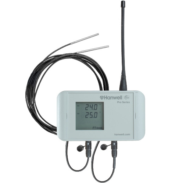
Part Code
|
Sensor Type
|
Transmitter
|
Transmitter Logs
|
Logger
|
EMS Compatibility
|
Add to EMS as:
|
4402-DU
|
Dual PT100 4 wire (-200oC to +110oC)
|
Yes
|
Yes
|
Yes
|
All Versions
|
Dual PT100
|
➢Part of the RL4000T Series ➢The RL4402-DU is a 4-wire PT100 unit fitted with 4-pin sockets for the external temperature sensors and an LCD display. ➢Temperature Measurement Range: -200°C to +110°C ➢Probes are available separately. ➢Datasheet |
RL4413-DU Transmitter/Sensor
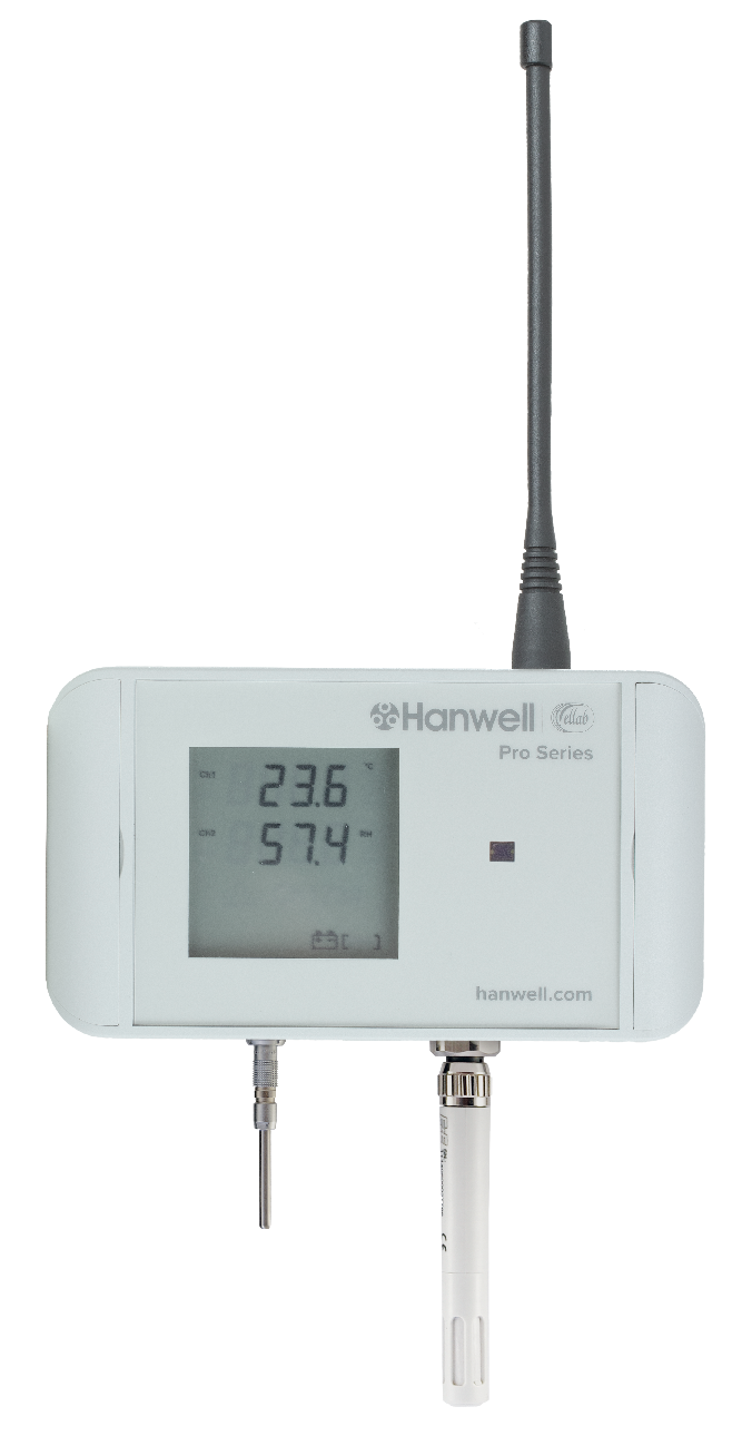
Part Code
|
Sensor Type
|
Transmitter
|
Transmitter Logs
|
Logger
|
EMS Compatibility
|
Add to EMS as:
|
4413-DU
|
Thermistor, Relative Humidity (RH) and
LUX (digital)
|
Yes
|
Yes
|
Yes
|
All versions
|
Thermistor/RH/Digital
|
➢Product Code: RL4413-DU-434.075 ➢Part of the Hanwell Pro RL4000RHT Series ➢The RL4413-DU RH/T/LUX Transmitter/Sensor is a highly accurate Temperature, Relative Humidity and LUX measurement unit, using an RH probe, Y300 thermistor and integral digital* LUX sensor. Note: The LUX is monitored by a digital sensor which only distingishes between light and dark and does not give a value for the brightness of the incident light.
➢Temperature Measurement Range: -20°C to +60°C ➢Humidity Measurement Range: 0 to 100% RH non-condensing. ➢Datasheet |
ML4109-DU RH/T Outdoor Transmitter/Sensor
Part Code
|
Sensor Type
|
Transmitter
|
Transmitter Logs
|
Logger
|
EMS Compatibility
|
Add to EMS as:
|
M4109-DU
|
Relative Humidity (RH) & Temperature
|
Yes
|
Yes
|
Yes
|
All Versions
|
Thermistor/RH
|
➢Product Code: ML4109-DU-434.075 ➢Part of the Hanwell Pro ML4000RHT Series ➢The ML4109 Outdoor RH/T Radio Transmitter provides highly accurate temperature and humidity measurement using an RH/T probe. ➢Temperature Measurement Range: -20°C to +60°C ➢Datasheet |
|
Hanwell Pro Sensor-Transmitters/Data Loggers - Spare Parts and Accesories
•Y055 - USB A TO USB Mini 2m Black •88706 - Battery 3.6V •Y119 - Wall mounting bracket •Y119-SA - Self Adhesive Wall mounting bracket •Y119-MSO - Magnetic stand off bracket •Y119-MSO-150 - 150mm extended Magnetic stand off bracket •Y060 3m - 3 channel linear sensor cable •Y060-1 - 3m 2 channel linear sensor cable •Y060-2 - 3m 2 channel linear sensor cable •Y058 - Quick transmit dongle |