Contents
Editing a Zone's Sensors
To edit a Zone's Sensors:
1.Click on the Sites radio button.
2.Either:
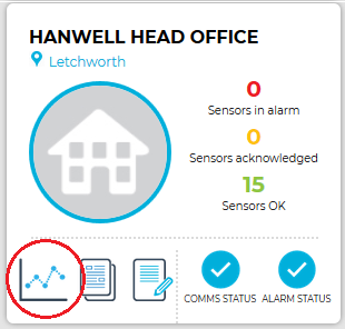
Click on the View Data icon on the relevant Site's Dashboard icon. See Figure 714 below:
Figure 714
Or:
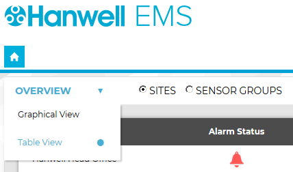
i.Select Table View from the OVERVIEW drop down menu. See Figure 715 below:
Figure 715
•The Sites Table View window is displayed. See Figure 716 below:
Figure 716
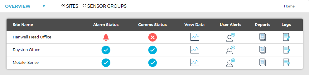
ii.On the Sites Table View window, click on the View Data icon associated with the Site you wish to view the Zones for. See Figure 717 below:
Figure 717

•In both cases, a Live View window is displayed for the selected Site, showing the Sensors associated with the first Zone listed. See Figure 718 below:
Figure 718
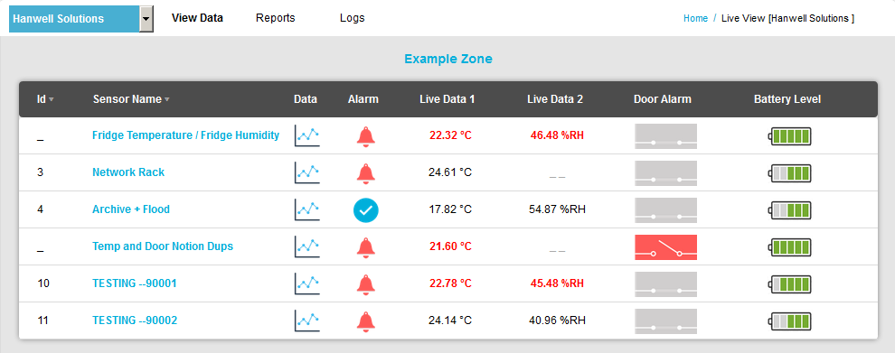
➢ To select another Zone, click here.
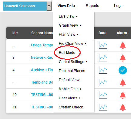
3.Select Edit Mode from the main View Data menu. See Figure 719 below:
Figure 719
•The Editing and Configuration window is displayed. See Figure 720 below: Figure 720
•By default, the Editing and Configuration window for the Zone at the top of the left-hand menu is displayed. •To display another Zone's Editing and Configuration window, click on the entry for the required Zone in the left-hand menu. For an example, see Figure 721 below: Figure 721
4.Select [Edit] in the line corresponding to the sensor to be Edited in the Zone's Editing and Configuration window to display the Edit Sensor window. Figure 722 below: Figure 722
5.Edit the displayed details as required. 6.Click on the Update button. •The sensor's details are updated and you are returned to the Zone's Editing and Configuration window. |


•The Edit Mode window is displayed. See Figure 723 below:
Figure 723
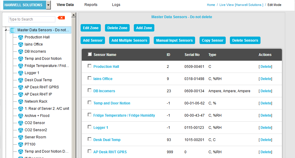
•By default, the Edit Mode window for the Zone at the top of the left-hand menu is displayed.
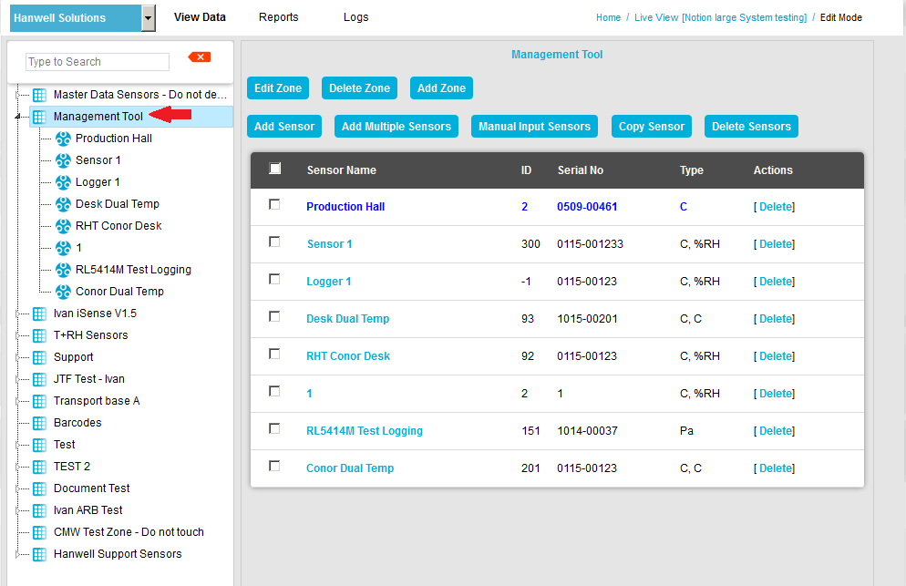
•To display another Zone's Edit Mode window, click on the entry for the required Zone in the left-hand menu. For an example. See Figure 724 below:
Figure 724
| Note: | Edit Mode is only available if you have the correct access Permissions. If you do not have the correct access Permissions, the following message window will be displayed. See Figure 725 below: |
Figure 725
4.Either:
i.In the left-hand list of the Zone's Edit Mode window, click on the small 'arrow' symbol to display a list of the Sensors associated with the Zone. See Figure 726 below:
Figure 726
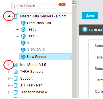
ii.In the left-hand list, click on the required Sensor's icon, i.e.: ![]() .
.
Or:
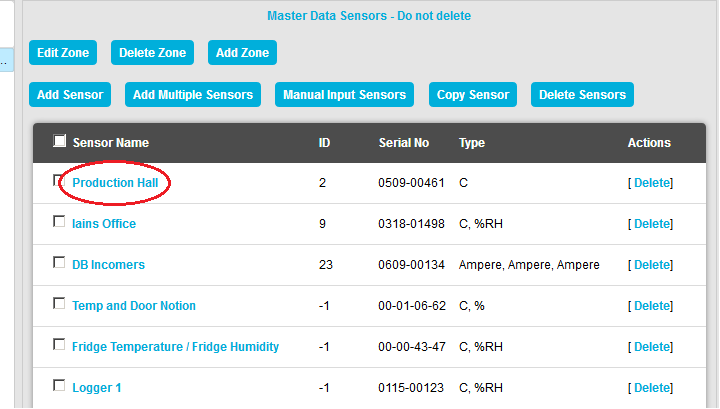
In table in the Zone's Edit Mode window, click on the required Sensor's name in the Sensor Name column. See Figure 727 below:
Figure 727
•The Edit Mode window for the selected Sensor is displayed. See Figure 728 below:
Figure 728
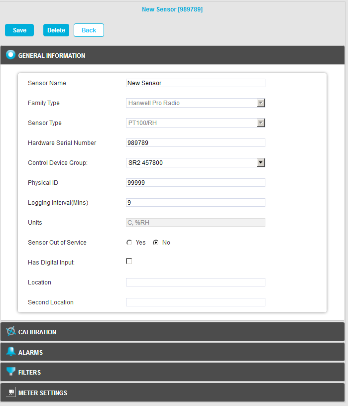
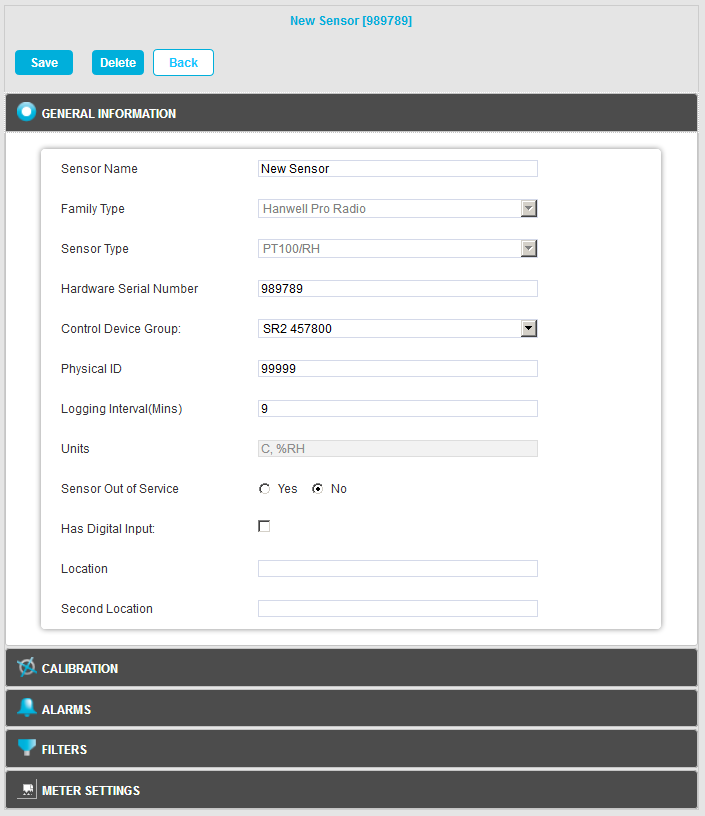
5.Edit the displayed details as required:
•Sensor Name
Here you can type a name for the Sensor that means something in relation to either the type of measurement that the Sensor is making or the location, for example, RH/T Room 1 or Room 1.
For this example we are going to call our Sensor, 'RH/T Room 1'.
This is the Transmitter's Serial Number and can be found on the back of the transmitter.
You can either:
Enter the Serial Number in the dialog box in the following format: 0113-00001
Or:
Enter a 0 (zero).
If a 0 (zero) is entered, the Serial Number will be filled in automatically by the EMS Management Application when the Sensor is synchronised. For details see Document: IM6000 EMS Remote Management Tool User Guide.
➢The Control Device Group is the wireless receiving device that will receive the data from the transmitters.
➢The Control Device Group is selected from the drop-down menu.
oSelect the Control Device Group which corresponds to the Site and is compatible with the wireless transmitters used at that Site.
oFor more details see the Adding Control Devices section.
oFor this example, we are going to select Hanwell.
•Physical ID
➢This is the Unique Sensor ID, it can be in the range 1 to 255.
➢For this example we are going to select Sensor 1.
➢If the Physical ID is already used by another Sensor, the System will suggest the next available ID.
•Logging Interval (Mins)
➢The time, in minutes, between the Sensor's Logging/Parameter Sampling events.
•Send Interval
➢For certain Families of Sensor (for example iSense) this Value sets the interval between times when logged data is sent to the Hanwell Remote Data Service.
| CAUTION: | Changing the Send Interval and Internal Logging Interval (Mins) values in EMS (Edit Mode) for an iSense Unit will flush any unsent data from the iSense Unit’s memory. |
The Optional Details are:
•Units
This is the measurement Units for each of the channels for the Sensor/Transmitter.
➢These cannot be changed here as they are set by the Sensor/Transmitter install.
•Sensor Out of Service
This feature allows you to temporally take a Sensor out of service. This is useful if the Sensor/Transmitter is measuring something that is turned off for a period and monitoring is not required.
➢It avoids alarms being generated while the Sensor/Transmitter is not required.
➢Out of Service Sensors are displayed with blue text in the Live View.
•Has Digital Input
Checking this box registers that at least one of the Sensor's channels monitors a digital signal.
•Location
Second Location
The Location and Second Location fields allow you to put notes against the Sensor to assist with physically locating the Sensor/Transmitter within a building.
➢These are aide-mémoires only, serve no operational function within the software and are not mandatory.
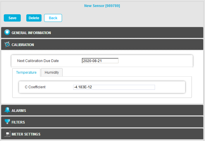
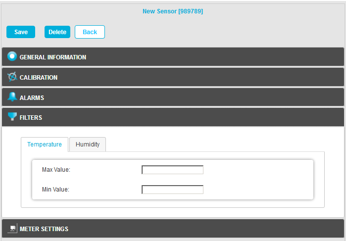
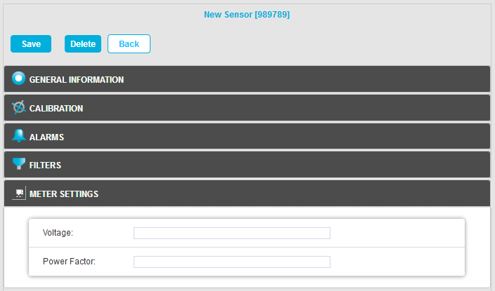
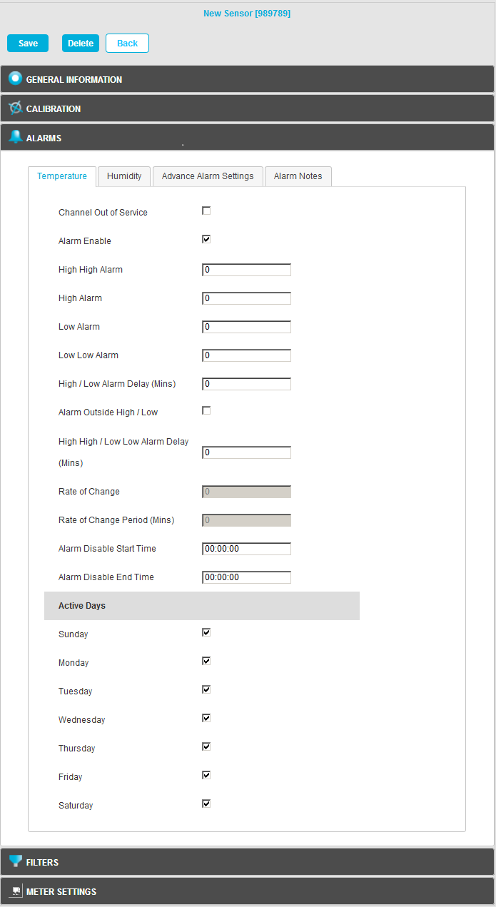
•Sensor Property functionality is accessed by clicking on the relevant panes at the bottom of the Edit Mode window. See Figure 729 below (Click on the relevant image to navigate to information on the parameters for each Sensor Property):
Figure 729
6.Once you are happy with the details click on the Save button to save the Sensor's edited details.
•Click on the Back button to cancel editing the Sensor's details.
•The Sensor's details are updated and you are returned to the Zone's Edit Mode window.
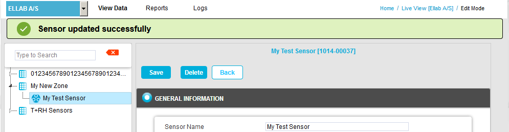
•A green dialog box is displayed in the Edit Mode window confirming that the Sensor has been updated successfully. See Figure 730 below:
Figure 730
![]() 16 Channel Digital Sensor/Device Type (e.g. GutterWatch)
16 Channel Digital Sensor/Device Type (e.g. GutterWatch)
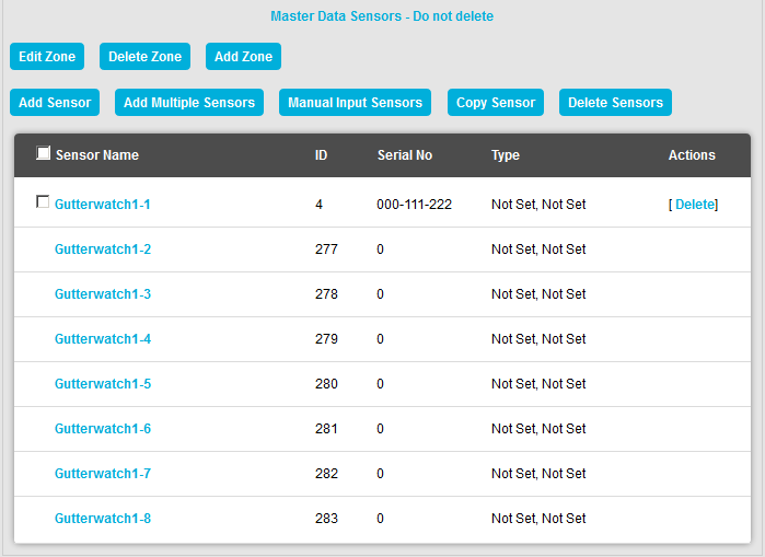
If a 16 Channel Digital Device/Sensor such as GutterWatch has been added/assigned to a Zone it will be represented in EMS as eight Dual Channel Sensors with a 'Master' Sensor defining the General Information parameters for all eight. See Figure 731 below: Figure 731
•Parameters in the General Information pane are only editable for the 'Master' Sensor. •For the other seven 'non-master' Sensors, parameters can be edited in the Calibration, Alarms and Filters panes. |