Navigation:
System Configuration Sensors > Sensors >> Replacing a Faulty Sensor
Replacing a Faulty Sensor

Contents
Having physically swapped the faulty Sensor for a new one, configure it to work with EMS as follows:
| Note: | The following information assumes that you are logged in via an account with Edit Mode privileges. |
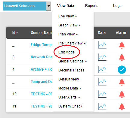
1.From the required Site's Live View window, select Edit Mode from the main View Data menu. See Figure 781 below:
Figure 781
•The Editing and Configuration window is displayed. See Figure 782 below: Figure 782
•By default, the Sensor and Zone editing/configuration window for the Zone at the top of the left-hand menu is displayed. •To display another Zone's Editing and Configuration window, click on the entry for the required Zone in the left-hand menu. For an example, see Figure 783 below: Figure 783
2.In the Zone's Editing and Configuration window, select [Edit] in the line corresponding to the Sensor that has been replaced. •The Edit Sensor window for the replaced Sensor is displayed. See Figure 784 below: Figure 784
3.Change the Hardware Serial Number to that of the new Sensor. •The Hardware Serial Number can be found on the back of the transmitter and should be entered in the following format, 0113-00001. Note: You can enter a 0 (zero) for the Hardware Serial Number. If a 0 (zero) is entered, the Hardware Serial Number will be filled in automatically by the EMS Management Application when the sensor is synchronised (see 6. below). 4.If applicable, change the value of the Sensor Physical ID. 5.Click on the Update button. •The sensor's details are updated and you are returned to the Zone's Editing and Configuration window. 6.Depending on the installation, use the EMSRemoteManagementTool utilities to synchronise the new Sensor with EMS; updating its Serial Number and Calibration details and setting its Physical ID. •See Document: IM6000 EMS Remote Management Tool manual for more details. |


•The Edit Mode window is displayed. See Figure 785 below:
Figure 785
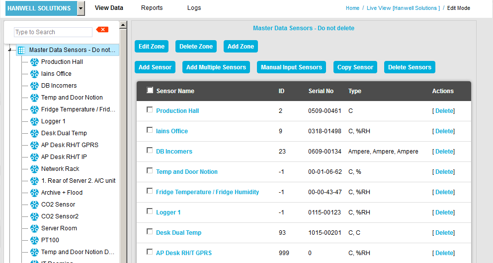
•By default, the Sensor and Zone editing/configuration window for the Zone at the top of the left-hand menu is displayed.
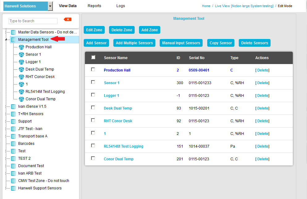
•To display another Zone's Edit Mode window, click on the entry for the required Zone in the left-hand menu. For an example, see Figure 786 below:
Figure 786
2.Either:
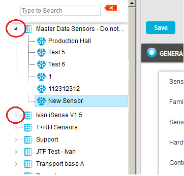
i.In the left-hand list of the Zone's Edit Mode window, click on the small 'arrow' symbol to display a list of the Sensors associated with the Zone. See Figure 787 below:
Figure 787
ii.In the left-hand list, click on the required Sensor's icon ![]() .
.
Or:
In table in the Zone's Edit Mode window, click on the Sensor to be replaced in the Sensor Name column. See Figure 788 below:
Figure 788
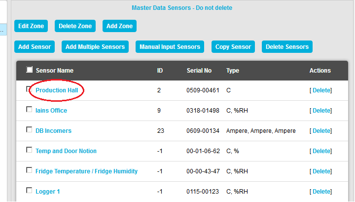
•The Edit Mode window for the Sensor to be replaced is displayed. See Figure 789 below:
Figure 789
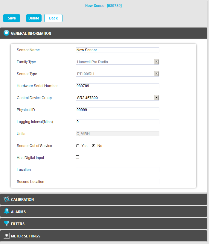
3.Change the Hardware Serial Number to that of the new Sensor.
•The Hardware Serial Number can be found on the back of the transmitter and should be entered in the following format, 0113-00001.
4.If applicable, change the value of the Sensor's Physical ID.
5.Click on the Save button.
•The Sensor's details are updated and you are returned to the Zone's Edit Mode window.
•A message is displayed confirming that the Sensor has been updated successfully. See example in Figure 790 below:
Figure 790
![]()
6.Depending on the installation, use the EMSRemoteManagementTool utilities to synchronise the new Sensor with EMS; updating its Serial Number and Calibration details and setting its Physical ID.
•See IM6000 EMS Remote Management Tool manual for more details.