Navigation:
System Configuration Sensors > Sensors > Add/Assign Sensors to a Zone >> Associating a Sensor with a CR3 (NW) Device
Associating a Sensor with a CR3 (NW) Control Device

Contents
To associate a Sensor with a CR3 (NW) Control Device, once it has been added to a Zone, as outlined in Add/Assign Sensors:
1.From the Add Sensor window, select the Control Device Group, created previously in the Create Device Group window. See Figure 707 below: Figure 707
2.Set the required Sensor Data Logging Interval, the period of time over which measurements are taken by the sensors, in the CR3 (NW) memory as follows: i.Click on Edit Mode in the View Data Main Menu Bar entry. See Figure 708 below: Figure 708
ii.In the left hand menu of the displayed winodw, expand the Zone, Sensor and Properties menu entries. See Figure 709 below: Figure 709
iii.Click on the General entry in the left-hand menu. See Figure 710 below: Figure 710
•The General Information window is shown. See Figure 711 below: Figure 711
3.Enter the required Sensor Data Logging Interval into the Logging Interval (Mins): field. •When setting the Logging Interval, be aware that if the measured parameter values are likely to change rapidly, then the Sensor Data Logging Interval needs to be short enough to ensure that the full range of parameter value variation is captured. 4.Click Update to save the changes. Note: iSense sensors are handled as a special sensor in EMS. |


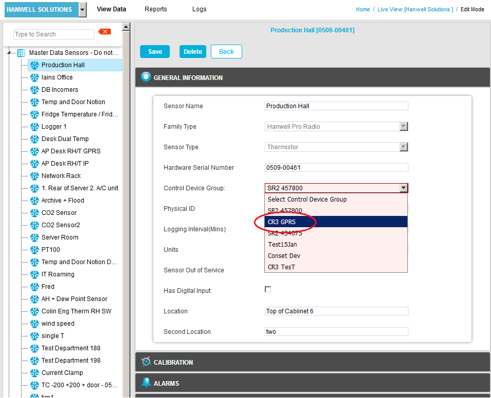
1.From the GENERAL INFORMATION pane in the Add Sensor window, select the Control Device Group, created previously in the Create a Device Group window. See Figure 712 below:
Figure 712
2.Enter the required Sensor Data Logging Interval into the Logging Interval (Mins): field. See Figure 713 below:
Figure 713
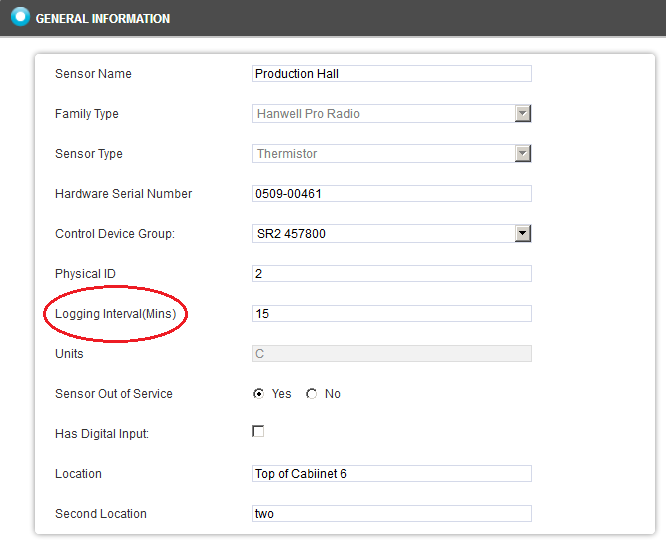
•When setting the Logging Interval, be aware that if the measured parameter values are likely to change rapidly, then the Sensor Data Logging Interval needs to be short enough to ensure that the full range of parameter value variation is captured.
3.Click Save to save the changes.
Note: |
iSense Sensors are handled as a special Sensor in EMS. •They are not part of a Control Device Group and have a special PID value of zero. •EMS collects iSense data by making an outgoing TCP/IP connection to the Hanwell Remote Data Service. As this connection is made to the standard HTTP Port (8081) on the Hanwell Remote Data Service, the System operates in the vast majority of cases with no need to make Network or Firewall configuration changes. |