Navigation:
EMS Outputs > 3rd Party Equipment Control (MS1000) > Conset >> Introduction to Conset
Introduction to Conset

Contents
•Conservation Heating Control Parameters
•Domestic and Comfort Settings/Domestic Days
•Control Mixer Sensor Settings
Conset Conservation Heating Control
The purpose of Conservation Heating Control is to help preserve culturally important objects and buildings by their maintaining humidity and temperature within acceptable bounds, without adding or removing water via humidification or dehumidification.
The reasoning behind this is as follows:
•Dealing with water within historic buildings presents a flood risk.
•Humidification equipment is expensive to buy and maintain.
There is a strong correlation between Relative Humidity (RH) and Temperature; therefore, given that variations in RH are much more important than variations in temperature for many collections, it is often possible to use an existing heating System to control RH to an acceptable degree, for most of the year, in a temperate climate such as the UK.
Given that heating plant will be needed anyway and that, without RH control, the heating will often dry the object's/building's environment beyond what is desirable, this approach makes sense.
•If the RH is too high, there is a risk of damage to objects from mold growth.
•Variations in RH can cause expansion and contraction, as moisture is absorbed and released, leading to damage.
For many collections/properties these effects are far more significant than temperature variations over normal ambient range; therefore, RH stability around 54% is the primary aim of any such control function.
Where Conset is controlling heating, this can be used to drive down Relative Humidity (RH), by heating the air in a room.
However; temperatures must be maintained within certain limits.
•If temperatures drop too low then there is also the risk of frost, whereas too hot is unacceptable in a building and indeed expensive to achieve.
Conset enables the use of heating Systems to maintain the desired humidity for the preservation of heritage objects and, if required, supports conventional humidifiers and/or dehumidifiers. It does this whilst respecting temperature settings' upper and lower bounds as far as is physically possible.
As humidity control is the primary function of Conservation Heating Control; Conset will try to keep RH at around the Humidity Set Point for each Hanwell Temperature and Relative Humidity Control Sensor.
Conservation Heating Control Parameters
Upper Temperature
When Humidity exceeds the %RH Set Point, the heating will be turned on, and the room heated until either the humidity comes back into control or the Upper Temperature limit is reached.
The Upper Temperature Limit can be differentiated with one setting – Season Upper Temperature - when the property is open and another - Out of Season Upper Temperature - when the property is closed.
•If required, both Upper Temperature settings can be set to the same value.
Lower Temperature
The Lower Temperature setting is intended to provide frost protection; if the temperature drops below the lower temperature, the heating will be turned on regardless of the current humidity.
Though Conservation Heating Control is the primary method for controlling Relative Humidity via Conset, where the environment tends to be dry, Conset can be used to control humidifiers to maintain RH at the set point for each Sensor.
•Where a Control Sensor is used to control a humidifier, the only significant setting is the Minimum %RH setting.
In Control Systems, Hysteresis is used to prevent unwanted rapid switching around the point of control.
•As the humidity is reduced to the Set Point, the heating is turned off and/or the humidifier is turned on.
➢At this point, the humidity begins to rise again.
•This rise exceeds the Set Point, causing the heating to be turned on again and/or the humidifier to be turned off.
➢At this stage, the humidity quickly reduces to the Set Point and the heating is turned off again and/or the humidifier is turned on.
This process then repeats, with the heating and/or humidifier continually turning on and off, as the humidity oscillates around the Set Point.
Figure 1343 below shows a System without Hysteresis:
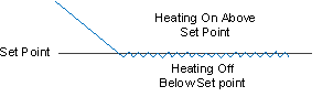
Figure 1343
Hysteresis works by adding Upper and Lower Set Points; a 'buffer zone' around the Set Point, so that a 'lag' is created between the heating and/or humidifier System(s) being turned on and off
•When humidity is above the Set Point, the Hysteresis Value is subtracted from the Set Point, so the heating remains on (or humidifier remains off) until the humidity reaches the Lower Set Point.
•Once the heating turns off (or humidifier turns on), the Hysteresis Value is added to the Set Point and the heating is only turned back on (or humidifier turned off) once the Upper Set Point is reached.
Figure 1344 below shows a System with Hysteresis:
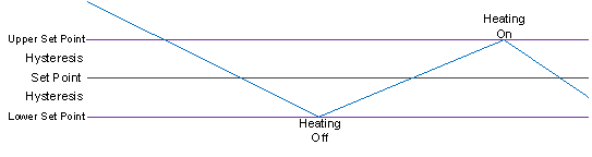
Figure 1344
Example:
Say we have a Humidity Set Point of 55%RH and a Hysteresis of 1%RH:
•If the humidity is high, then the heating will remain on (or humidifier remain off) until the humidity is driven down to 54%RH.
•When the humidity is low, the heating will remain off (or humidifier remain on) until the humidity reaches 56%RH.
The optimal values for the preservation of a building's fabric and contents may not be optimal for the comfort of any occupants of, or visitors to, the building and so might only be used outside the opening hours and outside the open season dates unless a manual override has been set and so, a second Comfort Heating Scheme, also employing temperature modulated control, could be defined for the building concerned.
•The Comfort Heating Scheme attempts to maintain the ambient temperature of the zone at the desired Steward Temperature i.e. comfortable for staff and visitors. This heating scheme would be employed during the opening hours and during the open season dates unless a manual override has been set.
Domestic and Comfort Settings/Domestic Days
Domestic and Comfort Settings are intended to provide override controls for rooms that maybe are used as offices, domestic areas or for a special event.
•It assumed that these rooms are cleared of objects of cultural value whist used as an office, or during the period that the special event is occurring and the Minimum %RH setting can be safely ignored.
•If, there are items of cultural value in the rooms used for offices or events, the Use Minimum %RH box can be selected and heating will be held off where humidity is too low.
•During the periods that Domestic and Comfort settings are active, the System will try to maintain the temperature set in the Domestic and Comfort Settings section of the Control Sensor Settings window.
For a one off special event, such as a party or wedding etc., the Comfort settings can be used as follows:
1.In the Domestic and Comfort Settings section of the Control Sensor Settings window, set:
•The event's required temperature;
•The event's start and end dates;
•The event's start and end times.
2.Check that Use Minimum %RH is correctly selected (if necessary).
3.Select Comfort Configuration Enabled.
4.Deselect Domestic Enabled in the Domestic Days section.
For office or domestic areas that are regularly occupied, perhaps on certain days, the Domestic Days settings can be used.
•In these areas, temperature control overrides RH control most of the time.
1.Set the required temperature and the start and end times that the room will be occupied (for 24hour occupation, set 00:00 to 23:59).
2.Check that Use Minimum %RH is blanked (default).
3.Deselect Comfort Configuration Enabled.
4.In the Domestic Days section, select the days of the week that the room will be occupied and select Domestic Enabled.
The Steward Temperature represents the minimum temperature that you would like to try to maintain in specific rooms when they are open to visitors and/or staff.
•The Steward Temperature is secondary to the Conservation Control. As such, if the humidity is below the Minimum % RH, the heating will not be turned on.
Steward temperature would only be applied during the opening times/days during the Open Season.
Normally these settings will be setup on commissioning and left as-is during normal operation.
To use these controls, click on the In Loop heater check box in the Secondary Loop Settings section of the Control Sensor Settings window.
These settings can be used to provide proportional control of a wet heating System.
•If Proportional Control is not used, set K and I values to 0.
•Control is provided by either a variable voltage or 4 to 20mA, signal from an MS1000 Analogue card.
The signal is used to control opening and closing of a variable valve which controls the loop flow, usually to one or more radiators.
The card is addressed by setting the Wet Mixer Card Number and Wet Mixer Channel fields in the Secondary Loop Settings window.
A PID Controller continuously calculates an Error Value e(t) as the difference between a desired set point and a measured process variable and applies a correction based on Proportional, Integral and Derivative terms.
The Controller attempts to minimise the error over time by adjustment of a Control Variable u(t), such as the position of a control valve, a damper or the power supplied to a heating element, to a new value, determined by a weighted sum:
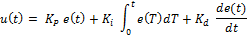
Where Kp , Ki and Kd are all non-negative and denote the coefficients for the Proportional, Integral and Derivative terms respectively (sometimes denoted P, I and D).
In this model:
| P | Accounts for present values of the error. For example, if the error is large and positive, the control output will also be large and positive. |
| I | Accounts for past values of the error. For example, if the current output is not sufficiently strong, the integral of the error will accumulate over time, and the controller will respond by applying a stronger action. |
| D | Accounts for possible future trends of the error, based on its current rate of change. |
In Conset:
K = Kp
I = Ki ;
•In common with most Systems, the Hanwell control System does not use derivative Kd .
In the Conset System the process variable is Temperature, which measured by the associated control Sensor.
Proportional Control's Use in Heating Control
For most heating control Systems, the rate of change is slow and on/off relay control will provide effective control, without the need for proportional outputs and valves.
Where proportional control is required; then from experience, it has been found that values of around 100 for K generally work best. I generally has very little effect on control - again due to the naturally slow rate of change in heating Systems - and can generally be left at 0.
The Mixer Valve Control is used to control a motorised valve to generate a Constant Temperature Secondary Loop. In this case, the Wet Mixer Card Number and Wet Mixer Channel fields in the Secondary Loop Settings window define the analogue output that controls the motorised valve on the loop associated with that Sensor.
| Note: | Mixer Valve Control signals must be via a hardwired MS1000 Card. |
See: Control Mixer Sensor Settings below.
The following sections cover more advanced heating control parameters; these should be configured by a Hanwell Engineer, in association with your heating contractor.
•Where Control Sensors have the In loop heating check box in the Secondary Loop Settings window selected, these Sensors will generate a Boiler Demand signal when heating is required.
❖The Boiler Demand signal is provided by an MS1000 card, addressed by setting the Boiler Demand Card and Boiler Channel fields in the Mixer System Details window.
| Note: | If the Card ID is less than 64, then the Boiler Demand signal will be transmitted to both wired and radio relay cards in the System. Care must be taken to ensure that there is not a 'clash' between radio and wired cards' ID numbers with respect to the Boiler Demand Card ID. |
•If not using a sensor to monitor the Control Sensor's Loop Temperature - i.e. using a Mixer sensor added in the Mixer Settings page - then the K and I values, and the Wet Mixer Card Number and Wet Mixer Channel, must all be set to 0.
These settings are used to duplicate real Sensors in software, where one Sensor is used to control two pieces of plant.
•An example would be a humidifier/dehumidifier combination where very tight control is required.
Ghost Sensors are rarely used; if required, ghost Sensors would be setup by Hanwell.
Each set of Control Mixer Sensor settings is used in conjunction with one or more Control Sensors.
•Control Sensors are linked to the Control Mixer Sensor settings by setting the Wet Mixer Card Number and Channel fields to address the same card and channel as set in the Mixer Card and Channel fields.
The defined control parameters allow the loop to stop heating in the event of no demand from associated radiator(s) or reduce heating where the loop temperature exceeds the specified Maximum Temperature limit.
•The analogue output control is either a variable voltage or 4 to 20mA from an MS1000 Analogue Card addressed by the Mixer Card and Channel field settings.
| Caution: | Do not add a Sensor as both a Mixer Sensor and a Control Sensor; CR3 loop control will not work properly if you do. |
| Note: | The CR3 NW can handle a maximum of 16 Mixer Settings. Be Aware that this means a maximum of 16 entries, NOT 16 Mixer Sensors. i.e. If a Dual Temperature sensors is paired with two Control Sensors - one on each temperature channel - then each channel represents a separate Mixer Setting . |
The Temperate Sensor and Channel specify a temperature channel on an RL4001-xxx.xxx or RL4002-xxx.xxx Sensor, used to monitor the loop temperature with a surface mounted temperature Sensor.
| Caution: | If the Flow Sensor is mounted too close to the boiler then the System may switch erratically. A minimum 2m downstream on the loop feed pipe is recommended. |
Where a loop supplies a single area under Conservation Heating Control, such as a large room, a Humidity Sensor can be associated with the Loop Control to reduce heating when the humidity is under control.
Conset can control the Secondary Loop Pump.
| Note: | Conset Does Not control the Primary Pump, this is the responsibility of the Boiler Control System. |
•The Pump Card and Channel fields address an MS1000 Relay Output to run the Secondary Loop Pump when demand is signaled.
•When demand is signaled from one or more associated Control Sensors, the pump will be run.
•When demand is no longer signaled, the pump will continue to run for the number of minutes specified in the Overrun Time field, before being turned off.
Control Sensors must be Thermistor RH Sensors.
You may use:
RL4000, RFBug or ML2000 Thermistor RH types.
•Add RL4000s as 'Thermistor/RH/Control' Sensor types and RFBugs as 'RF Bug Thermistor/RH/Control' Sensor types.
Mixer Sensors can be either Temperature or Thermistor RH Sensor types.
| Caution: | Mixer Sensors can be EITHER Temperature OR Thermistor RH Sensor types. Do not try to get around this by adding a Temperature Sensor as a Thermistor RH Sensor; it will cause unexpected CR3 behaviour. |