Navigation:
EMS Outputs > 3rd Party Equipment Control (MS1000) > Conset >> Control Setup (Conset)
Control Setup (Conset)

Contents
EMS's Control Setup (Conset) functionality is designed to allow the configuration of inputs to and outputs from CR3 (CR3 NW) Control Receivers.
Outputs from CR3 (CR3 NW) Control Receivers can be used to trigger the operation of 3rd party control devices (e.g. motorised heating System valves), either directly or via MS1000 Control Units.
•Conset is only used for configuring the Control Settings for CR3 (CR3 NW) Control Receivers.
•Once configured, a CR3 (CR3 NW) is autonomous, requiring no external software or network connection to operate, though a network connection will be initially required to allow Conset to connect to the CR3 (CR3 NW) Controller and configure it.
| Note: | Conset in EMS cannot be used to configure legacy CR3 controllers, these must be upgraded to CR3 controller to enable control from EMS; please contact your Local Distributor or Hanwell Sales for details. |
A typical application for which Conset could be used to configure Control Receiver inputs and outputs is the control of Relative Humidity (RH) for conservation purposes. For example: Two heating schemes, both employing temperature modulated control, could be defined for the building concerned: A Conservation Heating Scheme The Conservation Heating Scheme would attempt to maintain the ambient RH of the building the optimum value for the preservation of the building's fabric and contents. This value, however, may not be optimal for the comfort of any occupants of the building and so might only be used outside the opening hours and outside the open season dates unless a manual override has been set. Additionally, two temperature overrides could be used: •The maximum temperature is the highest the ambient temperature is allowed to reach. Even if the RH is above the %RH Setpoint, the temperature of the heating will not be increased. This is to ensure the room is not over-heated, leading to damage to building fabric/contents. •The minimum temperature is the lowest the ambient temperature is allowed to reach. Even if heating the zone will cause the RH to drop below the desired RH setpoint, the temperature of the heating will be increased. This is to ensure frost-protection, leading to damage to building fabric/contents. A Comfort Heating Scheme The Comfort Heating Scheme attempts to maintain the ambient temperature of the zone at the desired Steward Temperature i.e. comfortable for staff and visitors. This heating scheme would be employed during the opening hours and during the open season dates unless a manual override has been set. |
|
•Accessing Conset Functionality
Accessing Conset Functionality
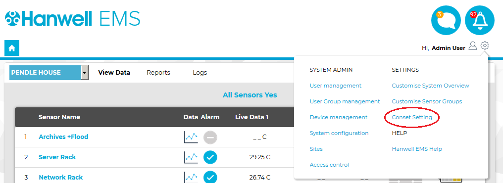
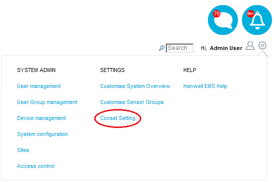
Conset functionality is accessed from within EMS as follows: 1.From the SETTINGS entry in the System drop down menu, select Conset Setting. See Figure 1345 below:
Figure 1345
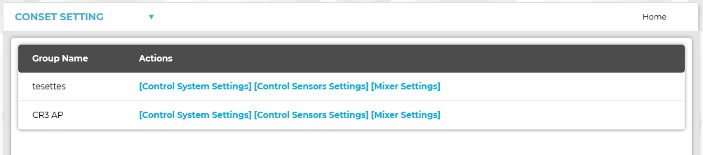
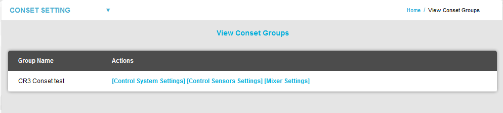
2.The View Conset Groups window is displayed, showing only CR3 (CR3 NW) Control Device Groups available for configuration by the Conset application via the [Control System Settings], [Control Sensors Settings] and [Mixer Settings] functions.
Figure 1346
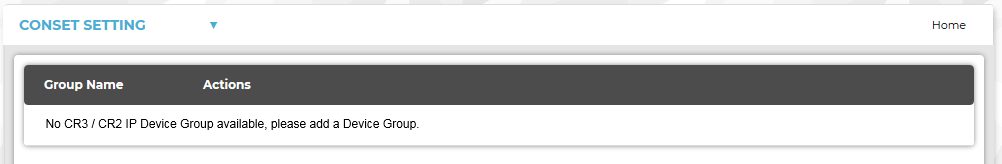
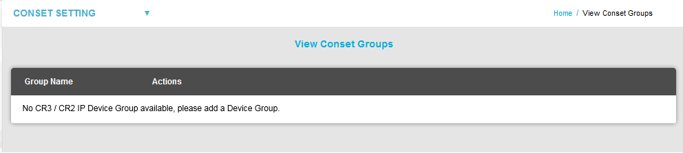
•If no CR3 (CR3 NW) Control Device Groups are available, the following window is displayed and you will need to add/define the required CR3 (CR3 NW) Control Device Groups. See Figure 1347 below:
Figure 1347
There are three types of setting available to a Conservation Heating Scheme in EMS to enable it to maintain the ambient Relative Humidity (RH) of an area at the desired %RH Setpoint (+/- the RH Hysterisis Setting) through the use of temperature modulated control: Covers the settings that will be the same for all Sensors (for example, house Opening Time and Closing Time). Covers the settings of each individual Sensor and includes parameters such as the %RH Setpoint. In wet heating systems where there is a primary boiler loop feeding into secondary heating circuits, the EMS system's outputs can contribute to maintaining the ambient RH by adjusting the position of the heating installation's mixer valve according to a Proportional-Integral (PI) algorithm using the K and I values set for the control channel via Conset.
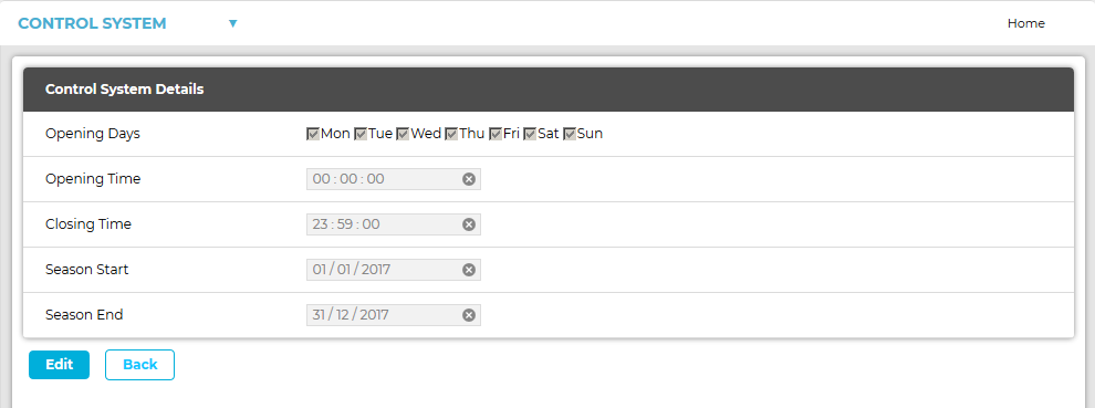
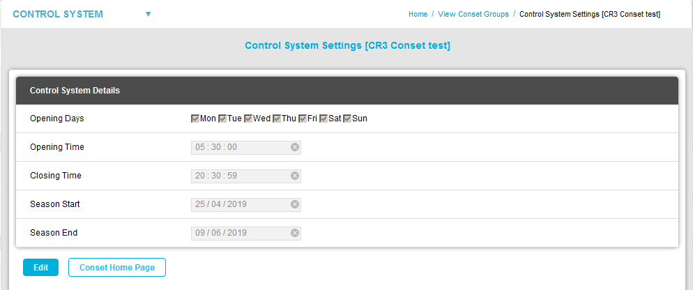
Adding or Editing Control System Settings for a Device/Control Group 1.Cick on [Control System Settings] adjacent to the required Control Group's entry in the View Conset Groups window. •The Control System Settings window is displayed for the selected Device/Control Group. See Figure 1348 below:
Figure 1348
2.Click on Edit. •The Edit Control System Details window is displayed with the Control System Details fields activated, allowing values to be entered. See Figure 1349 below:
Figure 1349
3.Edit the Control System Details as required.
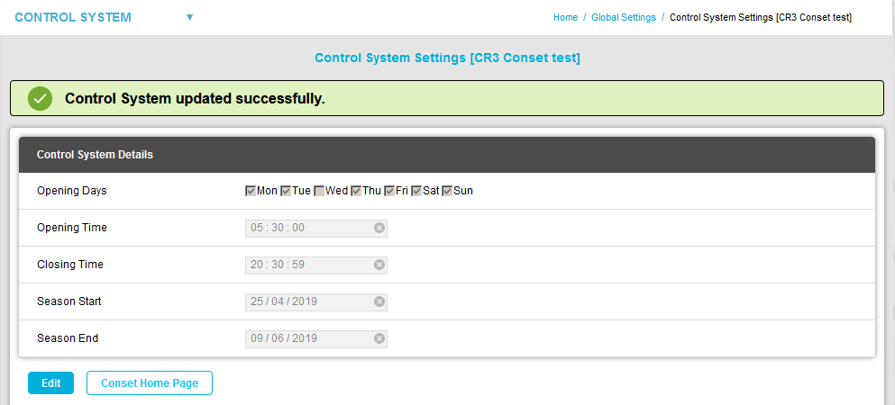
4.Click on the Save Changes button. See Figure 1349 above. •The edited Control System Details are saved and you are returned to the View Conset Groups window which displays a Control System updated successfully message. See Figure 1350 below:
Figure 1350
5.Click on the Back button to return to the Control System Settings window. Adding or Editing Control Sensor Settings for a Device/Control Group Click on [Control Sensors Settings] adjacent to the required Control Group's entry in the View Conset Groups window. •The Control Sensor Settings window for the selected Device/Control Group is displayed. See Figures 1351 and 1351 below:
Figure 1351
Figure 1352
From this window you can: •Edit a Control Sensor's Parameters To Add a Control Sensor to the Control Group: 1.In the Control Sensor Settings window, click on the Add Sensor button. •The Add Sensor window for the selected Control Group is displayed. See Figure 1353 below:
Figure 1353 2. Select a Sensor to use as a Control Sensor from the Sensor Name drop down list. •To add a new Sensor to the CR3(CR3 NW) Control Group and thereby make it available in the Sensor Name drop-down list, refer to: Add/Assign Sensors to a Zone and Associating a Sensor with a CR3/CR3 (NW) Device. 3.If necessary, edit the required Control Sensor Parameter values for the new Control Sensor. 4.Click on the Add Sensor tab. •The Control Sensor window is displayed with a confirmation message. See Figure 1354 below:
Figure 1354
In the Control Sensor Settings window, click on [Delete] in the Actions column on the row containing the Control Sensor to be deleted. See Figure 1355 below:
Figure 1355
•The selected Control Sensor is deleted. To Edit a Control Sensor's Parameters: 1.In the Control Sensor Settings window, click on [Edit] in the Actions column on the row containing the Control Sensor to be edited.
• Control Sensor Settings window is displayed for the selected Sensor, showing the same Control Sensor parameters, as displayed in the Add Sensor window above, and populated with the selected Control Sensor's parameter values. See Figure 1356: 2.Edit the selected Control Sensor's parameter values as required. 3.Click on the Save Changes button. •The new parameter values are saved and the Control Sensor window is displayed with a confirmation message. See Figure 1357 below: Figure 1357
Figure 1358
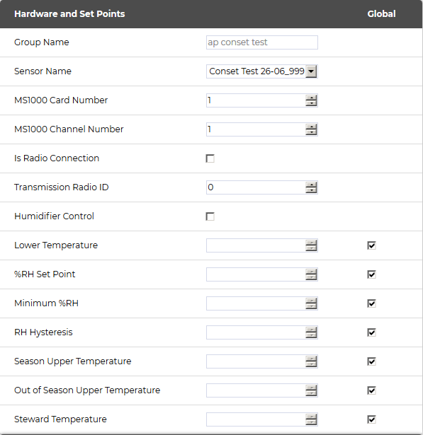
•Sensor Name The name of the new/edited Sensor. •MS1000 Card Number The card number of the MS1000 card controlled by the Sensor. If the Sensor is not controlling any outputs, this value should be set to 0 (zero). When this value is set to 0, no settings will be displayed. See Document Number: GD4619-1 MS1000 Control System Manual •MS1000 Channel Number Defines the MS1000 Output Channel that the selected Sensor is controlling. If the Sensor is not controlling any outputs, this should be set to 0 (zero). When this value is set to 0, no settings will be displayed.
•Is Radio Connection If the channel is controlled by radio transmissions from the CR3 (CR3 NW), the Is Radio Connection box should be checked. If the selected Sensor is hardwired to the Control Unit, rather than communicating wirelessly, the Is Radio Connection box should be left unchecked. •Transmission Radio ID The ID of the selected wireless Sensor. ➢Valid radio IDs are 1 to 254. ➢0 is used to represent radio off (no wireless connection). •Humidifier Control Check the Humidifier Control box if the selected Sensor is controlling a Humidifier. •Lower Temperature If this temperature is reached, the heating will automatically switch ON, regardless of the RH control requirements. This prevents under-heating or frost-damage of an area. ➢The default value is 15oC. This is the %RH point at which the heating will be turned on to drive down humidity, irrespective of the Steward Temperature setting. •Minimum %RH This setting overrides the Steward Temperature so that the RH never drops below the Minimum % RH set here. This is to prevent over-drying of an area. ➢The default value is 40%RH. This value represents the 'width'/sensitivity of the RH switching band. For Example: If a Hysteresis of 1 is set and the RH Setpoint is 55 (%) then the system will turn a heater on at 56%RH and off at 54%RH. •Season Upper Temperature If this Temperature value is reached during the Season dates/ times set in the Control System Settings [Control Group name], the heating will automatically switch off, regardless of the RH control requirements. This prevents the overheating of an area. ➢The default value is 22OC. •Out of Season Upper Temperature If this Temperature value is reached outside the Season dates/ times set in the Control System Settings [Control Group name], the heating will automatically switch off, regardless of the RH control requirements. This prevents the overheating of an area. ➢The default value is also 22OC. This option allows a different Lower Temperature value to be set during opening hours, for human comfort, and can be specified as part of a Comfort Heating Scheme. The software will use this setting during Opening Times/ Days (see the Site Details settings). ➢This value should be higher than the Lower Temperature setting. ➢The default value is 15OC.
It is possible to set temporary or permanent overrides of the optimum Conservation Heating settings - defined in the Hardware and Setpoints section - to create an optimum conservation environment to allow for events running outside standard opening hours or to accommodate offices or domestic areas. It assumed that these rooms are cleared of objects of cultural value whist they are being used as an office or during the period that the special event is occurring and, as a result, the Minimum %RH setting can be safely ignored. If there are item of cultural value in the rooms used for offices or events, then the Use Minimum %RH box can be selected and heating will be reduced where humidity is too low. During the periods that Domestic and Comfort settings are active, the System will try to maintain the temperature set in the Domestic and Comfort Settings section of the Control System Settings [Control Group name] window. If these parameters are enabled , by checking the Comfort Configuration Enabled box, the selected sensors will then be activated for Comfort Heating within the set time span. See Figure 1359 below: Figure 1359
•Comfort Configuration Enabled Ticking this box allows the setting of permanent or temporary overrides to conservation-optimum temperature settings. If this Minimum %RH value is reached during the Season dates/ times set in the Opening Hours Edit/View Control System window, the heating will automatically switch off, regardless of the RH control requirements. This prevents the overheating of an area. •Temperature Defines the Comfort/Steward Temperature. •Comfort Start Date Start date of the Comfort Temperature override of the settings. •Comfort End Date End date of the Comfort Temperature override of the Conservation Heating settings. •Comfort Start Time Start time of the Comfort Temperature override of the Conservation Heating settings. •Comfort End Time End time of the Comfort Temperature override of the Conservation Heating settings. If the Comfort override is being used to control an office or domestic area, tick the Domestic Enabled box and then select the relevant Domestic Days by ticking the appropriate boxes. The Comfort override will then operate between the Comfort Start Date and Comfort End Date on these days of the week for all future weeks. See Figure 1360 below: •No date settings are required in this case. Figure 1360
Domestic and Comfort Settings - Examples: One Off Special Event For a one-off special event, such as a party or wedding etc. the Comfort Settings can be used. 1.Set the required temperature; the Start and End dates and the Start and End times for the event in the Domestic and Comfort Settings section. 2.Check that Use Minimum %RH is correctly selected (if necessary), select Comfort Configuration Enabled and deselect Domestic Enabled in the Domestic Days section. Office or Domestic Areas For office or domestic areas that are regularly occupied, perhaps on certain days, the Domestic Days settings can be used. In these area temperature control overrides RH control most of the time. 1.Set the required temperature and the Start and End times between which the room will be occupied.
2.Check that Use Minimum %RH is blanked (normally) and deselect Comfort Configuration Enabled. 3.In the Domestic Days section, select the days of the week that the room will be occupied and then select Domestic Enabled. Normally these settings will be setup on commissioning and left as-is during normal operation. The Secondary Loop settings provided in this window can be used to provide proportional control of a wet heating system. Control is provided by either a variable voltage, or 4 to 20mA, signal from an MS1000 Analogue card, the signal being used to control the opening and closing of a motorised valve controlling the loop flow, usually to one or more radiators. •The MS1000 card and its output are defined by setting the Wet Mixer Card Number and Wet Mixer Channel fields. •PID Controller - K & I Constants Use of Proportional Control in Heating Control For most heating control systems, the rate of change is slow and on/off relay control will provide effective control, without the need for proportional control outputs and valves. Where Proportional Control is required then, from experience, it has been found that values of around 100 for K generally work best. I generally has very little effect on control - again due to the naturally slow rate of change in heating systems - and can generally be left at 0. •To use these controls, select the In Loop heater check box setting. See Figure 1361 below:
•In Loop Heater If the target device is a wet radiator (rather than electric) then this box should be checked. This is used to generate the Boiler demand signal. •Control Constant (Proportional K) This setting adjusts the proportional control's Controller Gain (Kc); a higher controller gain increasing the amount of proportional control action for a given error. ➢If the controller gain is set too high the control loop will begin oscillating and become unstable. ➢If the controller gain is set too low, it will not respond adequately to disturbances or Set Point changes. The Proportional Control Constant is the main parameter determining ongoing humidity control. •Control Constant (Integral I) This setting (the integral term) increases action in relation not only to the error but also the time for which it has persisted. So, if the applied force is not enough to bring the error to zero, this force will be increased as time passes. The Integral Control Constant refines ongoing humidity control towards zero static error.
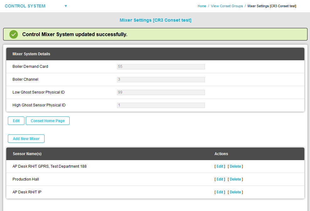
•Wet Mixer Card Number These values are used to control a motorised valve to generate a constant temperature secondary loop. ➢The Wet Mixer Card Number and Wet Mixer Channel fields define the analogue output (Card Number and Channel Number respectively) that controls the motorised valve on the loop associated with that sensor. See: Control Mixer Sensor Settings. Accessing Mixer Settings for a Control Device Group The following sections cover more advanced heating control parameters; these should be configured by a Hanwell Engineer, in association with your Heating Contractor. To Access Mixer Settings for a Control Device Group: Click on [Mixer Settings] adjacent to the required Control Device Group's entry in the View Conset Groups window. •The Mixer System Details window is displayed for the selected Control Device Group. See Figure 1362 below:
From this window you can: •Return to the View Conset Groups Window •Edit the Mixer System Details •Edit/Delete a Control Mixer Sensor 1.In the Mixer System Details window, click on the Add New Mixer button. •The Add New Mixer window is displayed. See Figure 1363 below: Figure 1363
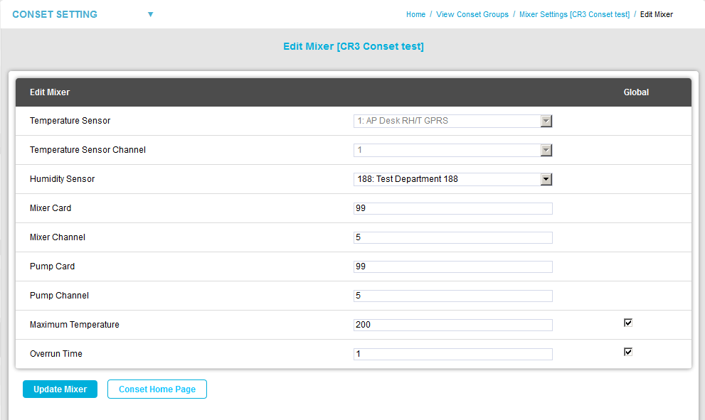
2.Select the Control Mixer parameters' values from the relevant drop down lists/up-down arrows: •Temperature Sensor The ID and name of the Sensor controlling the Secondary Loop. •Temperature Sensor Channel The channel of the Temperature Sensor on this loop. •Humidity Sensor The ID of the room sensor controlling this loop. •Mixer Card The ID of the MS1000 output card controlling this mixer (1 - 253). •Mixer Channel The channel of the MS1000 output card controlling this mixer (1 - 4). •Pump Card The ID of the MS1000 output card controlling the associated pump (1 - 253). •Pump Channel The channel of the MS1000 output card controlling the associated pump (1 - 4). •Maximum Temperature The maximum permitted secondary flow temperature (OC). •Overrun Time The time in minutes the pump should overrun after mixer valve closure. 3.Click on the Add Mixer button. •The new Mixer is added, the Add New Mixer window returns to a 'blank' state to facilitate the adding of further Mixers and a Control Mixer added successfully message is displayed. See Figure 1364 below:
Figure 1364
To Return to the View Conset Groups Window: Either: Click on View Conset Groups on the main menu bar. See Figure 1365 below:
Figure 1365
Or: Click on the Back button in the Add New Mixer window and subsequent windows until you are returned to the View Conset Groups window.
To Edit the Mixer System Details: 1.In the Mixer System Details section of the Mixer Settings [Control Device Group name] window, click on the Edit button. •The Edit Mixer window is displayed. See Figure 1366 below: Figure 1366
2.Edit the Mixer System Details: •Boiler Demand Card Defines the MS1000 Output Channel that controls the secondary heating circuit's boiler. Where Control Sensors have the In loop heating check box selected, those Sensors will generate a boiler demand signal when heating is required. The boiler demand signal is provided by a MS1000 Relay Card, configured by setting the Boiler Demand Card and Boiler Channel fields. • These settings are used to duplicate real sensors in software, where one sensor is used to control two pieces of plant. ➢An example would be a humidifier/dehumidifier combination where very tight control is required. ➢Ghost sensors are rarely used; if required, ghost sensors would be setup by Hanwell. The Low Ghost Sensor Physical ID defines the lower limit of the range of ghosted sensor IDs.
• These settings are used to duplicate real sensors in software, where one sensor is used to control two pieces of plant. •An example would be a humidifier/dehumidifier combination where very tight control is required. •Ghost sensors are rarely used; if required, ghost sensors would be setup by Hanwell. The High Ghost Sensor Physical ID value defines the upper limit of the range of ghosted sensor IDs.
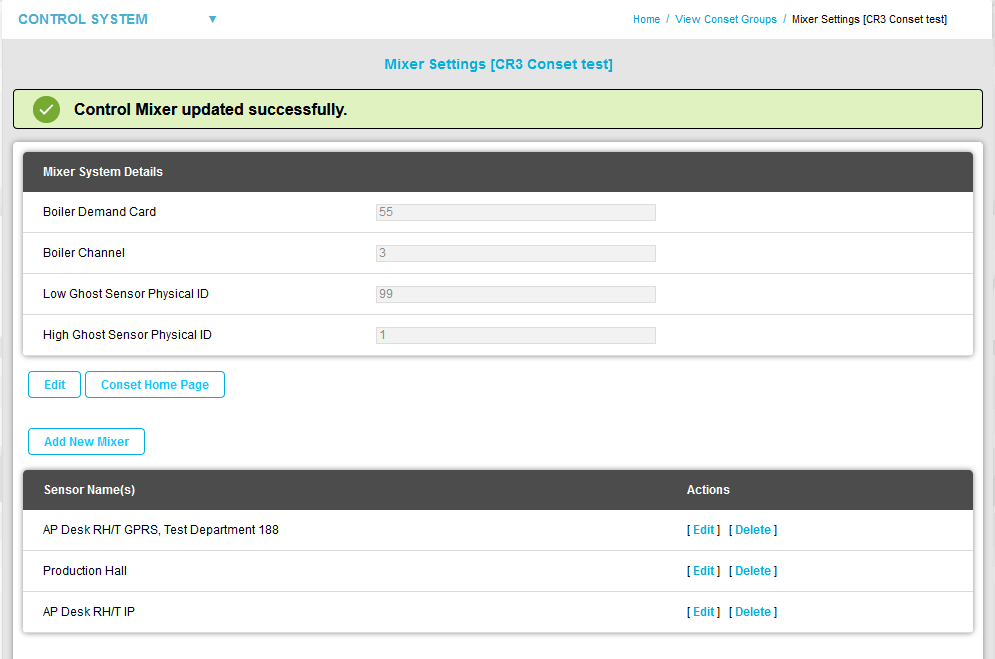
3.Click on Save Changes. •You are returned to the Mixer Settings [Control Device Group name] window displaying a Control Mixer System updated successfully message. See Figure 1367 below:
Figure 1367
To Edit/Delete a Control Mixer Sensor: To Edit a Control Mixer Sensor To Delete a Control Mixer Sensor To Edit a Control Mixer Sensor 1.In the Sensor Name(s) section of the Mixer System Details [Control Device Group name] window, click on the [Edit] link on the row containing the Control Mixer Sensor to be edited/deleted. See Figure 1367 •The Edit Mixer window is displayed. See Figure 1368:
Figure 1368
3.Select the required parameter values for the selected Control Mixer Sensor from the relevant drop down lists/up-down arrows. 4.Click on the Update Mixer button. •You are returned to the Mixer Settings [Control Device Group name] window displaying a Control Mixer updated successfully message. See Figure 1369 below:. See Figure 1369 below: Figure 1369
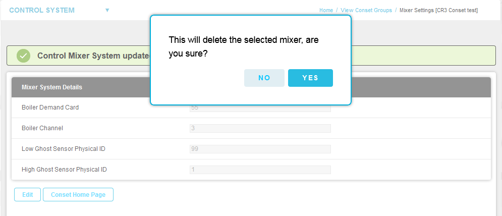
To Delete a Control Mixer Sensor 1.In the Actions column of the Sensor Name(s) section of the Mixer Settings [Control Device Group name] window , click on [Delete] in the row containing the sensor to be deleted. See Figure 1369 above. 2.Click on Yes in the displayed warning window. See Figure 1370 below: Figure 1370
•The selected Control Mixer Sensor is deleted. |
||||||||||||||||||||||||||||||||||||||||||||||||||||||||||||||||||||||||||||||
|
||||||||||||||||||||||||||||||||||||||||||||||||||||||||||||||||||||||||||||||
Conset functionality is accessed from within EMS as follows:
1.From the SETTINGS entry in the System drop-down menu, select Conset Setting. See Figure 1371 below:
Figure 1371
2.The View Conset Groups window is displayed, showing only CR3 (CR3 NW) Control Device Groups available for configuration by the Conset application via the [Control System Settings], [Control Sensors Settings] and [Mixer Settings] functions.
See Figure 1372 below:
Figure <%HMFIGURECOUNTER%>
•If no CR3 (CR3 NW) Control Device Groups are available, the following window is displayed and you will need to add/define the required CR3 (CR3 NW) Control Device Groups. See Figure 1372 below:
Figure 1372
There are three types of setting available to a Conservation Heating Scheme in EMS to enable it to maintain the ambient Relative Humidity (RH) of an area at the desired %RH Setpoint (+/- the RH Hysterisis Setting) through the use of temperature modulated control:
Covers the settings that will be the same for all Sensors (for example, house Opening Time and Closing Time).
Covers the settings of each individual Sensor and includes parameters such as the %RH Setpoint.
In wet heating Systems where there is a primary boiler loop feeding into secondary heating circuits, the EMS System's outputs can contribute to maintaining the ambient RH by adjusting the position of the heating installation's mixer valve according to a Proportional-Integral (PI) algorithm using the K and I values set for the control channel via Conset.
Adding or Editing Control System Settings for a Device/Control Group
1.Cick on [Control System Settings] adjacent to the required Control Group's entry in the View Conset Groups window.
•The Control System Settings window is displayed for the selected Device/Control Group. See Figure 1373 below:
Figure 1373
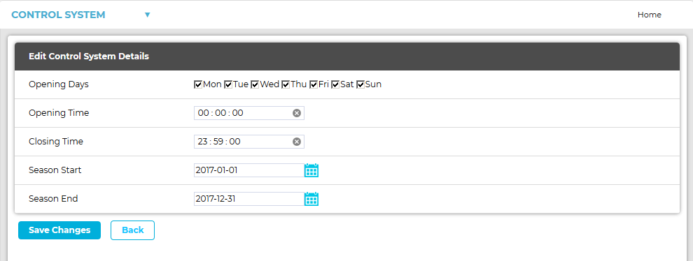
2.Click on Edit.
•The Edit Control System Details window is displayed with the Control System Details fields activated, allowing values to be entered. See Figure 1374 below:
Figure 1374
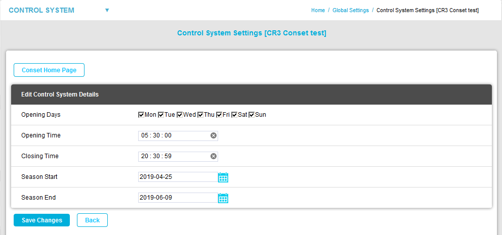
3.Edit the Control System Details as required.
Note: |
Only Day and Month values are used by CR3s; the Year value in any setting merely facilitates the use of the Date-Time Picker controls, the Year value is not sent to the CR3. |
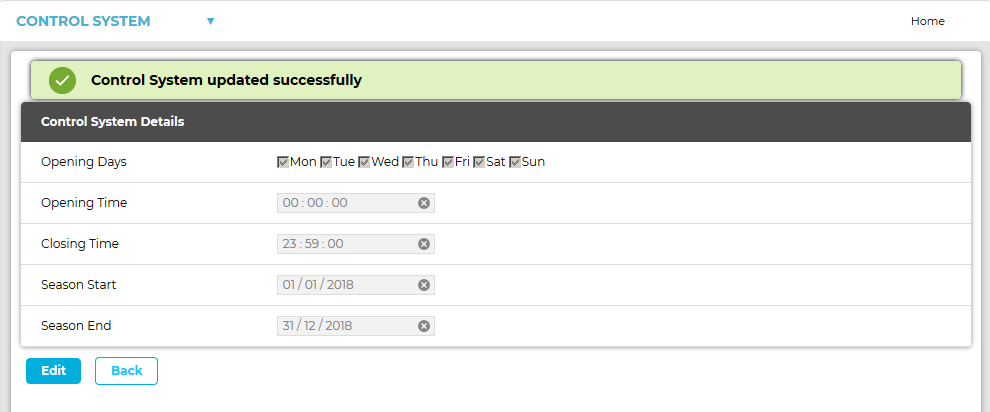
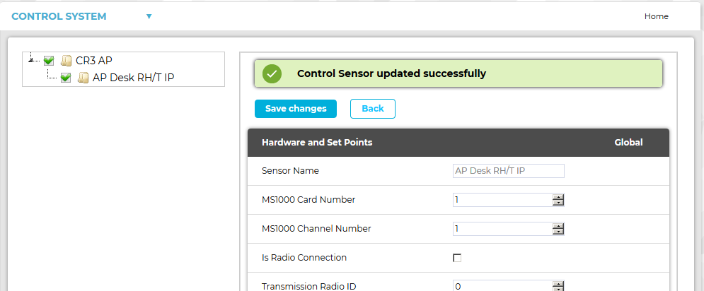
Click on the Save Changes button. See Figure 1374 above.
•The edited Control System Details are saved and you are returned to the View Conset Groups window which displays a Control System updated successfully message. See Figure 1375 below:
Figure 1375
5.Click on the Back button to return to the Control System Settings window.
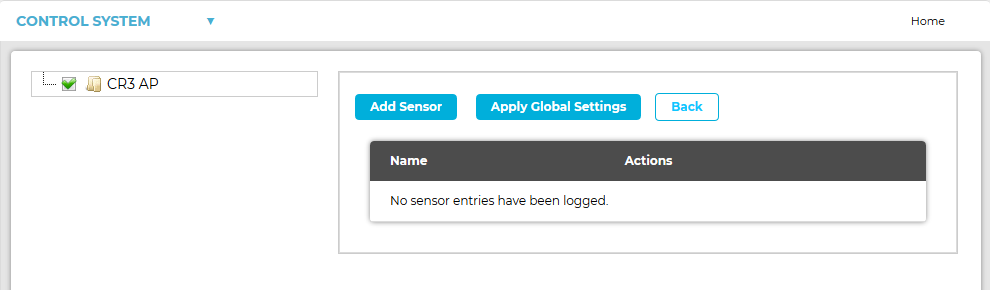
Adding or Editing Control Sensor Settings for a Device/Control Group
Click on [Control Sensors Settings] adjacent to the required Control Group's entry in the View Conset Groups window.
•The Control Sensor Settings [Device/Control Group Name] window for the selected Device/Control Group is displayed. See Figures 1376 below:
Figure 1376
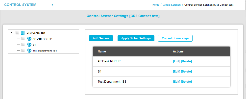
From this window you can:
•Edit a Control Sensor's Parameters
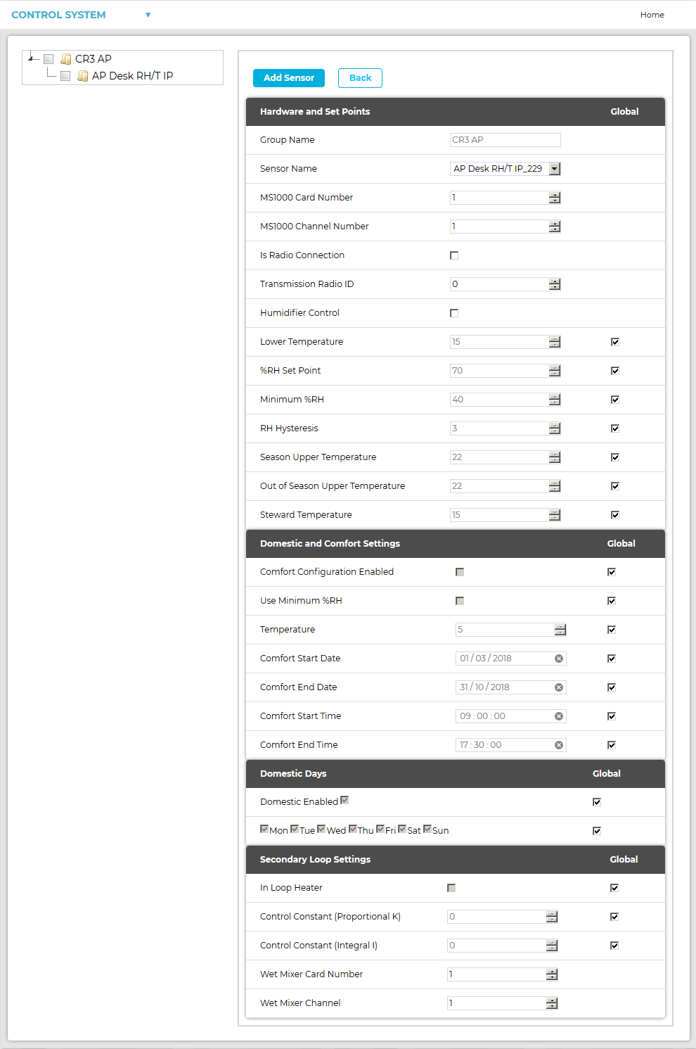
To Add a Control Sensor to the Control Group:
1.In the Control Sensor Settings window, click on the Add Sensor button.
•The Add Sensor window for the selected Control Group is displayed. See Figure 1377 below:
Figure 1377
2.Select a Sensor to use as a Control Sensor from the Sensor Name drop-down list in the Hardware and Set Points pane.
•To add a new Sensor to the CR3(CR3 NW) Control Group and thereby make it available in the Sensor Name drop-down list, refer to: Add/Assign Sensors to a Zone and Associating a Sensor with a CR3/CR3 (NW) Control Device.
3.If necessary, edit the required Control Sensor Parameter values for the selected Control Sensor.
•Click on the panes in Figure 1377 above to show details of each Control Sensor Parameter.
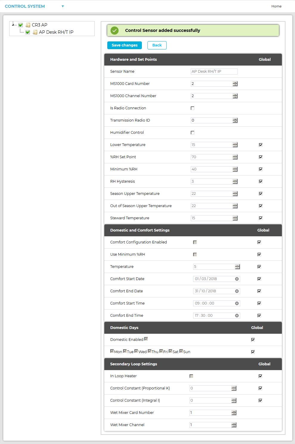
4.When all required changes have been completed, click on the Add Sensor button.
•A Control Sensor Settings window is displayed showing the new Control Sensor and a confirmation message. See Figure 1378 below:
Figure 1378
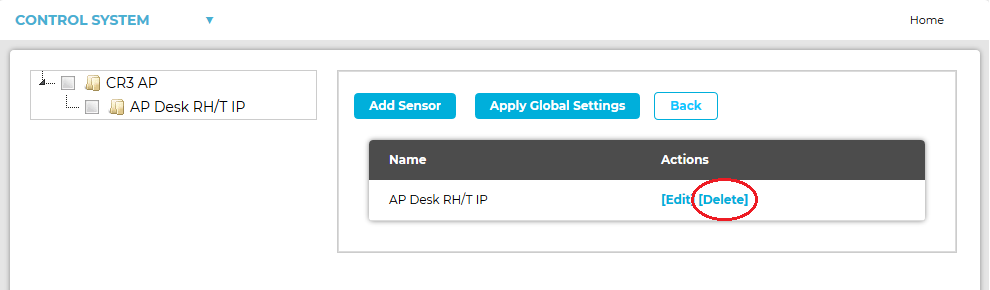
To Delete a Control Sensor from the Control Group:
In the Control Sensor Settings window, click on [Delete] in the Actions column on the row containing the Control Sensor to be deleted. See Figure 1379 below:
Figure 1379
•The selected Control Sensor is deleted.
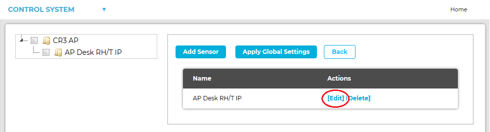
To Edit a Control Sensor's Parameters:
1.In the Control Sensor Settings window, click on [Edit] in the Actions column on the row containing the Control Sensor to be edited. See Figure 1380 below:
Figure 1380

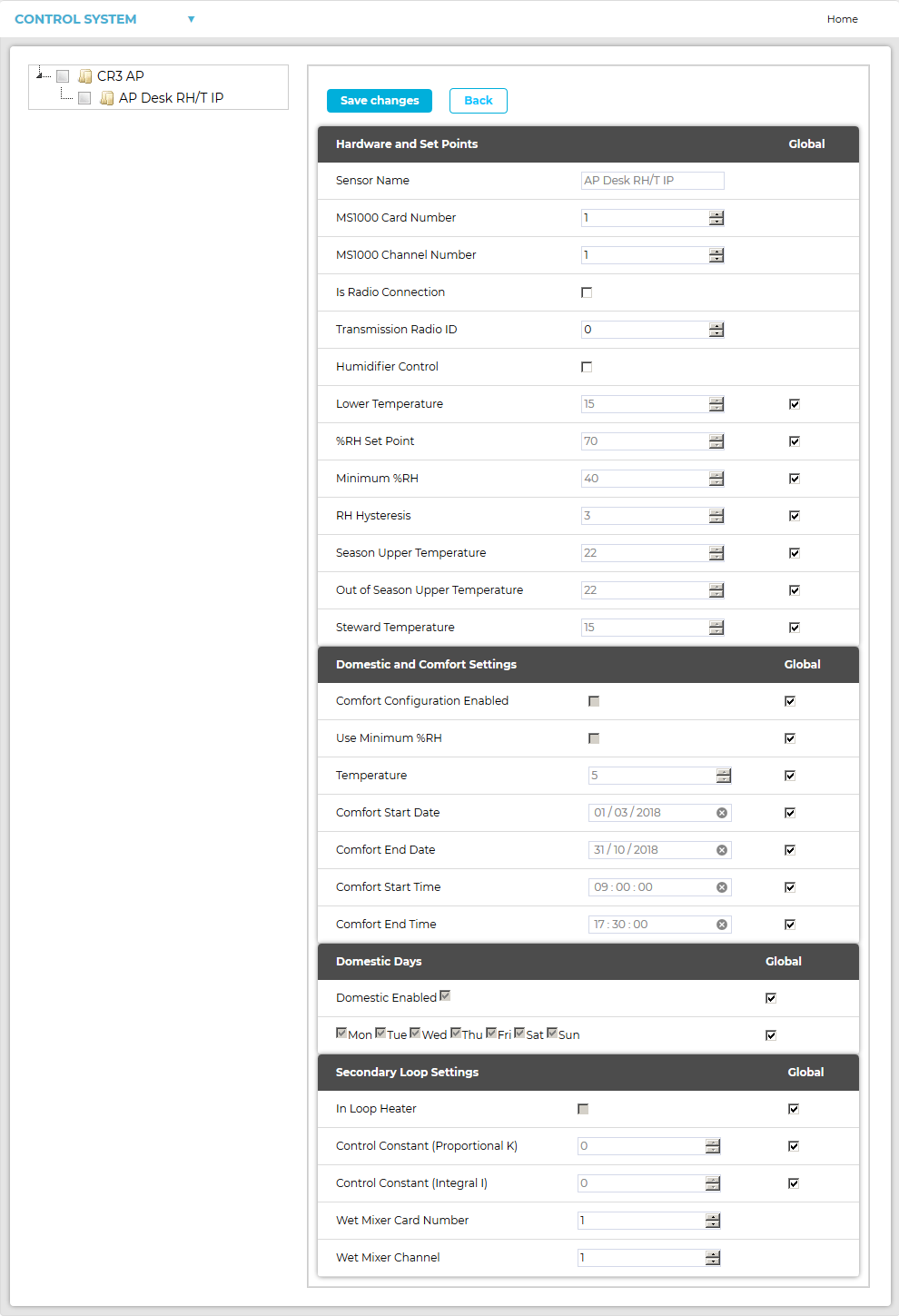
•Control Sensor Settings window is displayed for the selected Sensor, showing the same Control Sensor parameters, as displayed in the Add Sensor window above, and populated with the selected Control Sensor's parameter values. See Figure 1381:
2.Edit the selected Control Sensor's parameter values as required.
3.Click on the Save Changes button.
•The new parameter values are saved and the Control Sensor window is displayed with a confirmation message. See Figure 1382 below:
Figure 1382
Figure 1383
•Sensor Name
The name of the new/edited Sensor.
•MS1000 Card Number
The card number of the MS1000 card controlled by the Sensor.
If the Sensor is not controlling any outputs, this value should be set to 0 (zero). When this value is set to 0, no settings will be displayed.
See Document Number: GD4619-1 MS1000 Control System Manual
•MS1000 Channel Number
Defines the MS1000 Output Channel that the selected Sensor is controlling.
If the Sensor is not controlling any outputs, this should be set to 0 (zero). When this value is set to 0, no settings will be displayed.
| Note: | If transferring from a RadioLog System, Channel allocations will no longer be defined solely by a Channel Number but will, instead, be defined by the MS1000 Card Number and that Card's MS1000 Channel Number. See Figure 1383 above. > See the table below for Channel numbering definitions in RadioLog compared to EMS: |
RadioLog Channel Numbering |
EMS Channel Numbering |
|
RadioLog Channel Number |
EMS Card Number |
EMS Card Channel Number |
1 |
Card 1 |
1 |
2 |
Card 1 |
2 |
3 |
Card 1 |
3 |
4 |
Card 1 |
4 |
5 |
Card 2 |
1 |
6 |
Card 2 |
2 |
7 |
Card 2 |
3 |
8 |
Card 2 |
4 |
9 |
Card 3 |
1 |
10 |
Card 3 |
2 |
11 |
Card 3 |
3 |
12 |
Card 3 |
4 |
13 |
Card 4 |
1 |
14 |
Card 4 |
2 |
15 |
Card 4 |
3 |
16 |
Card 4 |
4 |
•Is Radio Connection
If the channel is controlled by radio transmissions from the CR3 (CR3 NW), the Is Radio Connection box should be checked.
If the selected Sensor is hardwired to the Control Unit, rather than communicating wirelessly, the Is Radio Connection box should be left unchecked.
•Transmission Radio ID
The ID of the selected wireless Sensor.
➢Valid radio IDs are 1 to 254.
➢0 is used to represent radio off (no wireless connection).
•Humidifier Control
Check the Humidifier Control box if the selected Sensor is controlling a Humidifier.
•Lower Temperature
If this temperature is reached, the heating will automatically switch ON, regardless of the RH control requirements. This prevents under-heating or frost-damage of an area.
➢The default value is 15oC.
This is the %RH point at which the heating will be turned on to drive down humidity, irrespective of the Steward Temperature setting.
•Minimum %RH
This setting overrides the Steward Temperature so that the RH never drops below the Minimum % RH set here. This is to prevent over-drying of an area.
➢The default value is 40%RH.
This value represents the 'width'/sensitivity of the RH switching band.
For Example: If a Hysteresis of 1 is set and the RH Setpoint is 55 (%) then the System will turn a heater on at 56%RH and off at 54%RH.
•Season Upper Temperature
If this Temperature value is reached during the Season dates/ times set in the Control System Settings [Control Group name], the heating will automatically switch off, regardless of the RH control requirements. This prevents the overheating of an area.
➢The default value is 22OC.
•Out of Season Upper Temperature
If this Temperature value is reached outside the Season dates/ times set in the Control System Settings [Control Group name], the heating will automatically switch off, regardless of the RH control requirements. This prevents the overheating of an area.
➢The default value is also 22OC.
This option allows a different Lower Temperature value to be set during opening hours, for human comfort, and can be specified as part of a Comfort Heating Scheme.
The software will use this setting during Opening Times/ Days (see the Site Details settings).
➢This value should be higher than the Lower Temperature setting.
➢The default value is 15OC.
| Note: | The, optional, Min % RH value overrides the Steward Temperature so that the Relative Humidity never drops below the Minimum % RH set here. This is to prevent over-drying of an area. The default value is 40% RH. |
It is possible to set temporary or permanent overrides of the optimum Conservation Heating settings - defined in the Hardware and Setpoints section - to create an optimum conservation environment to allow for events running outside standard opening hours or to accommodate offices or domestic areas.
It assumed that these rooms are cleared of objects of cultural value whist they are being used as an office or during the period that the special event is occurring and, as a result, the Minimum %RH setting can be safely ignored.
If there are item of cultural value in the rooms used for offices or events, then the Use Minimum %RH box can be selected and heating will be reduced where humidity is too low.
During the periods that Domestic and Comfort settings are active, the System will try to maintain the temperature set in the Domestic and Comfort Settings section of the Control System Settings [Control Group name] window.
If these parameters are enabled , by checking the Comfort Configuration Enabled box, the selected Sensors will then be activated for Comfort Heating within the set time span. See Figure 1384 below:
Figure 1384
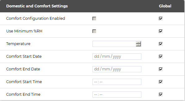
•Comfort Configuration Enabled
Ticking this box allows the setting of permanent or temporary overrides to conservation-optimum temperature settings.
If this Minimum %RH value is reached during the Season dates/ times set in the Opening Hours Edit/View Control System window, the heating will automatically switch off, regardless of the RH control requirements. This prevents the overheating of an area.
•Temperature
Defines the Comfort/Steward Temperature.
•Comfort Start Date
Start date of the Comfort Temperature override of the Conservation Heating settings.
•Comfort End Date
End date of the Comfort Temperature override of the Conservation Heating settings.
•Comfort Start Time
Start time of the Comfort Temperature override of the Conservation Heating settings.
•Comfort End Time
End time of the Comfort Temperature override of the Conservation Heating settings.
Note: |
Only Day and Month values are used by CR3s; the Year value in any setting merely facilitates the use of the Date-Time Picker controls, the Year value is not sent to the CR3. |
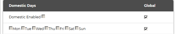
If the Comfort override is being used to control an office or domestic area, tick the Domestic Enabled box and then select the relevant Domestic Days by ticking the appropriate boxes. The Comfort override will then operate between the Comfort Start Date and Comfort End Date on these days of the week for all future weeks. See Figure 1385 below:
•No date settings are required in this case.
Figure 1385
Domestic and Comfort Settings - Examples:
One Off Special Event
For a one-off special event, such as a party or wedding etc. the Comfort Settings can be used.
1.Set the required temperature; the Start and End dates and the Start and End times for the event in the Domestic and Comfort Settings section.
2.Check that Use Minimum %RH is correctly selected (if necessary), select Comfort Configuration Enabled and deselect Domestic Enabled in the Domestic Days section.
Office or Domestic Areas
For office or domestic areas that are regularly occupied, perhaps on certain days, the Domestic Days settings can be used. In these area temperature control overrides RH control most of the time.
1.Set the required temperature and the Start and End times between which the room will be occupied.
| Note: | For 24 hour occupation, set 00:00 to 23:59. |
2.Check that Use Minimum %RH is blanked (normally) and deselect Comfort Configuration Enabled.
3.In the Domestic Days section, select the days of the week that the room will be occupied and then select Domestic Enabled.
Normally these settings will be setup on commissioning and left as-is during normal operation.
The Secondary Loop settings provided in this window can be used to provide proportional control of a wet heating System.
Control is provided by either a variable voltage, or 4 to 20mA, signal from an MS1000 Analogue card, the signal being used to control the opening and closing of a motorised valve controlling the loop flow, usually to one or more radiators.
•The MS1000 card and its output are defined by setting the Wet Mixer Card Number and Wet Mixer Channel fields.
•PID Controller - K & I Constants
Use of Proportional Control in Heating Control
For most heating control Systems, the rate of change is slow and on/off relay control will provide effective control, without the need for proportional control outputs and valves.
Where Proportional Control is required then, from experience, it has been found that values of around 100 for K generally work best. I generally has very little effect on control - again due to the naturally slow rate of change in heating Systems - and can generally be left at 0.
•To use these controls, select the In Loop heater check box setting. See Figure 1386 below:
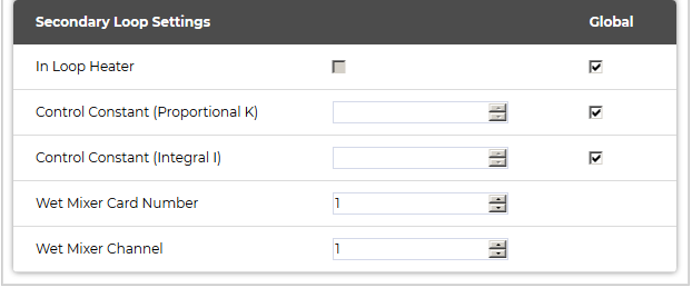
•In Loop Heater
If the target device is a wet radiator (rather than electric) then this box should be checked.
This is used to generate the Boiler demand signal.
•Control Constant (Proportional K)
This setting adjusts the proportional control's Controller Gain (Kc); a higher controller gain increasing the amount of proportional control action for a given error.
➢If the controller gain is set too high the control loop will begin oscillating and become unstable.
➢If the controller gain is set too low, it will not respond adequately to disturbances or Set Point changes.
The Proportional Control Constant is the main parameter determining ongoing humidity control.
•Control Constant (Integral I)
This setting (the integral term) increases action in relation not only to the error but also the time for which it has persisted. So, if the applied force is not enough to bring the error to zero, this force will be increased as time passes.
The Integral Control Constant refines ongoing humidity control towards zero static error.
| Note: | If the output channel is an analogue card controlling a mixer valve in a wet heating System then the K and I coefficients of the PI control algorithm are set here, otherwise they MUST be left at 0. |
•Wet Mixer Card Number
Wet Mixer Channel
These values are used to control a motorised valve to generate a constant temperature secondary loop.
➢The Wet Mixer Card Number and Wet Mixer Channel fields define the analogue output (Card Number and Channel Number respectively) that controls the motorised valve on the loop associated with that Sensor.
See Control Mixer Sensor Settings.
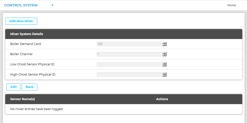
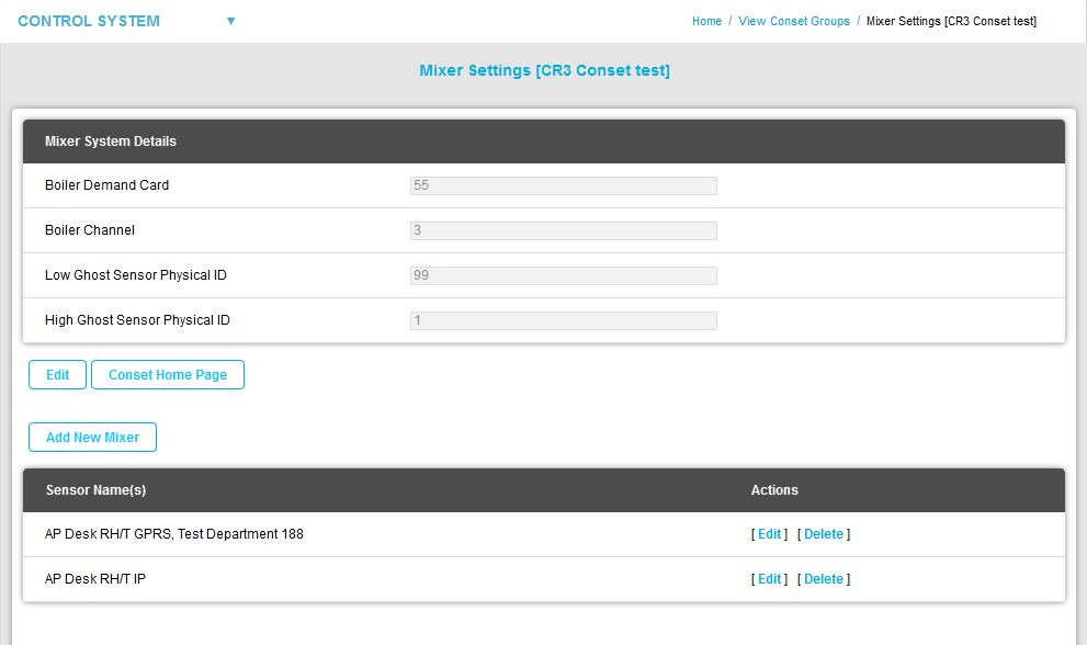
Accessing Mixer Settings for a Control Device Group
The following sections cover more advanced heating control parameters; these should be configured by a Hanwell Engineer, in association with your Heating Contractor.
To Access Mixer Settings for a Control Device Group:
Click on [Mixer Settings] adjacent to the required Control Device Group's entry in the View Conset Groups window.
•The Mixer Settings [Device/Control Group Name] window is displayed for the selected Control Device Group. See Figure 1387 below:
From this window you can:
•Return to the View Conset Groups Window
•Edit the Mixer System Details
•Edit/Delete a Control Mixer Sensor
1.In the Mixer System Details window, click on the Add New Mixer button.
•The Add New Mixer window is displayed. See Figure 1388 below:
Figure 1388
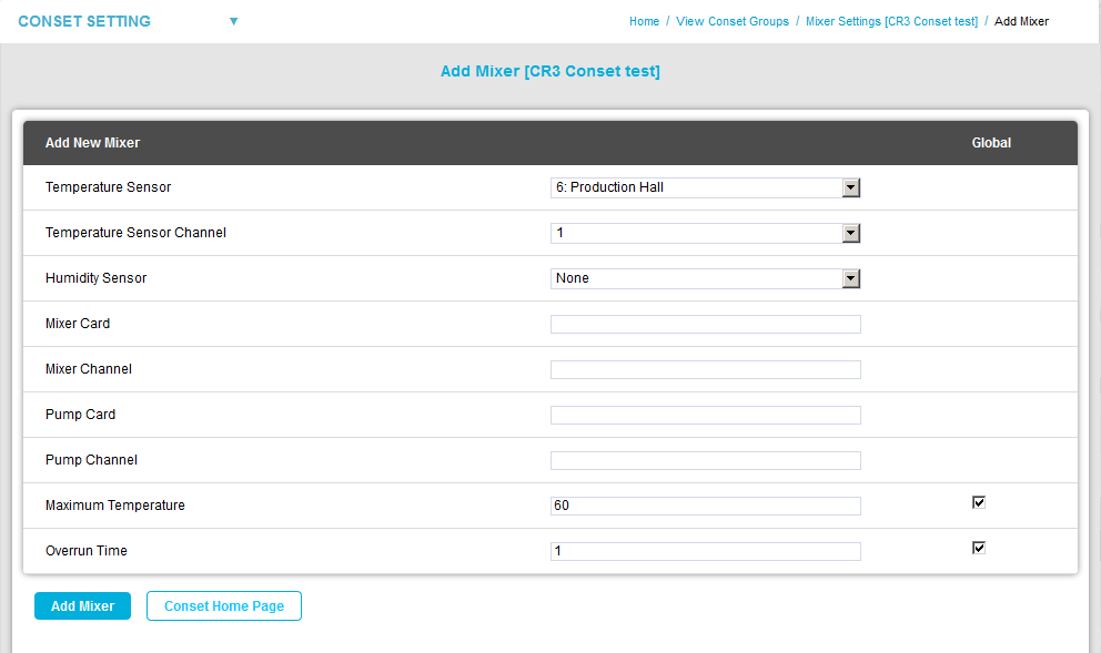
2.Select the Control Mixer parameters' values from the relevant drop-down lists/up-down arrows:
•Temperature Sensor
The ID and name of the Sensor controlling the Secondary Loop.
•Temperature Sensor Channel
The channel of the Temperature Sensor on this loop.
•Humidity Sensor
The ID of the room Sensor controlling this loop.
•Mixer Card
The ID of the MS1000 output card controlling this mixer (1 - 253).
•Mixer Channel
The channel of the MS1000 output card controlling this mixer (1 - 4).
•Pump Card
The ID of the MS1000 output card controlling the associated pump (1 - 253).
•Pump Channel
The channel of the MS1000 output card controlling the associated pump (1 - 4).
•Maximum Temperature
The maximum permitted secondary flow temperature (OC).
➢Tick the check box in the Global column if the value set for the Maximum Temperature is to apply to all Sensors in the Control Group.
•Overrun Time
The time in minutes the pump should overrun after mixer valve closure.
➢Tick the check box in the Global column if the value set for the Overrun Time is to apply to all Sensors in the Control Group.
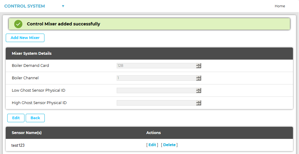
3.Click on the Add Mixer button.
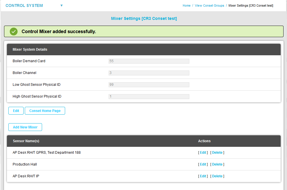
•The new Mixer is added, the Add New Mixer window returns to a state facilitating the addition of further Mixers and a Control Mixer added successfully message is displayed. See Figure 1389 below:
Figure 1389
To Return to the View Conset Groups window:
•Click on View Conset Groups on the main menu bar. See Figure 1390 below:
Figure 1390

To Edit the Mixer System Details:
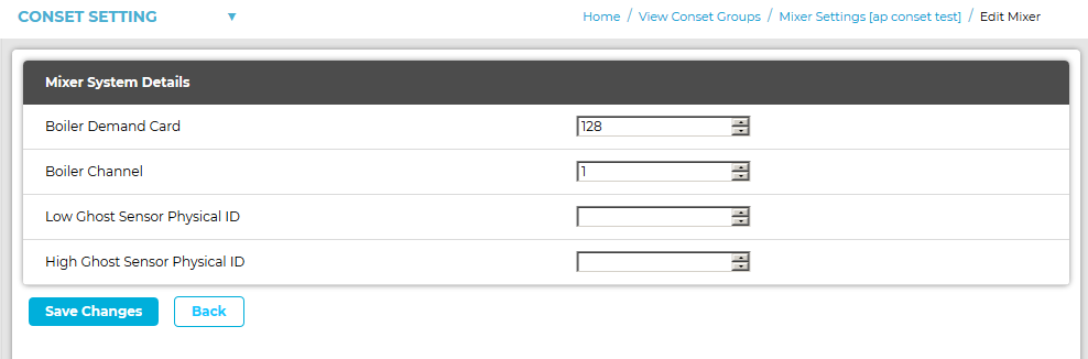
1.In the Mixer System Details section of the Mixer Settings [Control Device Group name] window, click on the Edit button.
•The Edit Mixer window is displayed . See Figure 1391 below:
Figure 1391
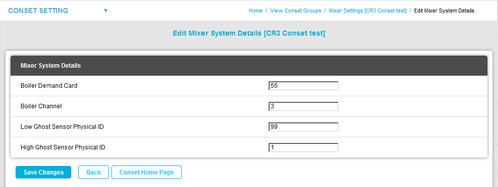
2.Edit the Mixer System Details:
Defines the MS1000 Output Channel that controls the secondary heating circuit's boiler. Where Control Sensors have the In loop heating check box selected, those Sensors will generate a boiler demand signal when heating is required. The boiler demand signal is provided by a MS1000 Card, configured by setting the Boiler Demand Card and Boiler Channel fields. |
These settings are used to duplicate real Sensors in software, where one Sensor is used to control two pieces of plant. ➢An example would be a humidifier/dehumidifier combination where very tight control is required. ➢Ghost Sensors are rarely used; if required, ghost Sensors would be setup by Hanwell. The Low Ghost Sensor Physical ID defines the lower limit of the range of ghosted Sensor IDs. Ghost Sensors: In EMS, one Sensor is associated with one channel only. However, there are circumstances where more than one control output is required per Sensor. Examples are when a humidifier AND dehumidifier/heater are in the same room. Sensors can be ghosted to allow two channels to be controlled by one RH Sensor, i.e. more than one control output per Sensor. This can allow one Sensor to control two pieces of equipment without installing a second physical Sensor. Note 1:Each ghosted Sensor occupies 2 ID slots, which means that both of these slots are unavailable for other uses. Note 2:The maximum Sensor ID available for control is ID 253. Note 3:The setup for the ghosting function will be performed by the commissioning engineer. |
•High Ghost Sensor Physical ID
These settings are used to duplicate real Sensors in software, where one Sensor is used to control two pieces of plant. oAn example would be a humidifier/dehumidifier combination where very tight control is required. ➢The High Ghost Sensor Physical ID value defines the upper limit of the range of ghosted Sensor IDs. Ghost Sensors: In EMS, one Sensor is associated with one channel only. However there are circumstances where more than one control output is required per Sensor. Examples are when a humidifier AND dehumidifier/heater are in the same room. Sensors can be ghosted to allow two channels to be controlled by one RH Sensor, i.e. more than one control output per Sensor. This can allow one Sensor to control two pieces of equipment without installing a second physical Sensor.
|
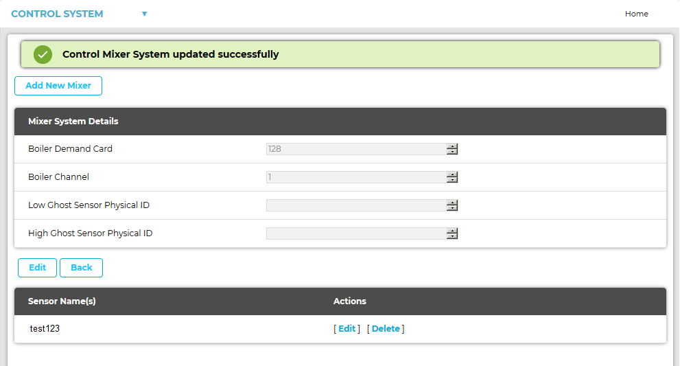
3.Click on Save Changes.
•You are returned to the Mixer Settings [Control Device Group name] window displaying a message stating: 'Control Mixer System updated successfully'. See Figure 1392 below:
Figure 1392
To Edit/Delete a Control Mixer Sensor:
•To Edit a Control Mixer Sensor
•To Delete a Control Mixer Sensor
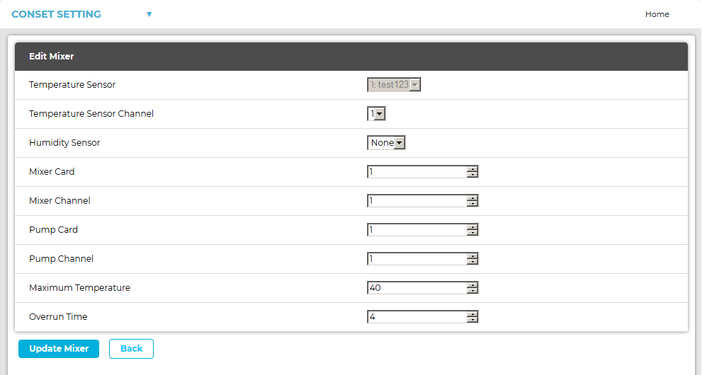
To Edit a Control Mixer Sensor
1.In the Sensor Name(s) section of the Mixer Settings [Control Device Group name] window, click on the [Edit] link on the row containing the Control Mixer Sensor to be edited/deleted. See Figure 1392
•The Edit Mixer [Control Device Group name] window is displayed. See Figure 1393:
Figure 1393
2.Select the required parameter values for the selected Control Mixer Sensor from the relevant drop-down lists/up-down arrows.
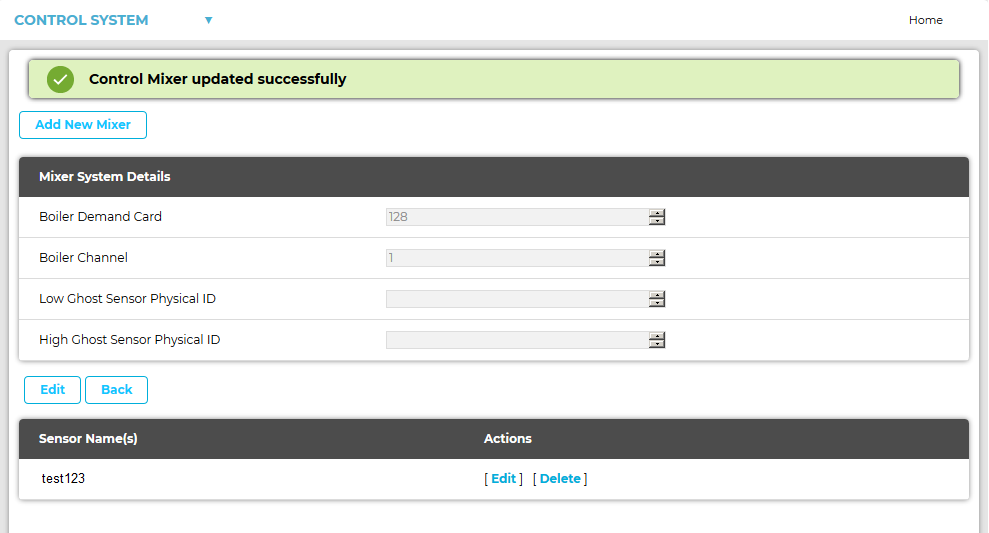
3.Click on the Update Mixer button.
•You are returned to the Mixer Settings [Control Device Group name] window displaying a Control Mixer updated successfully message. See Figure 1394 below:
Figure 1394
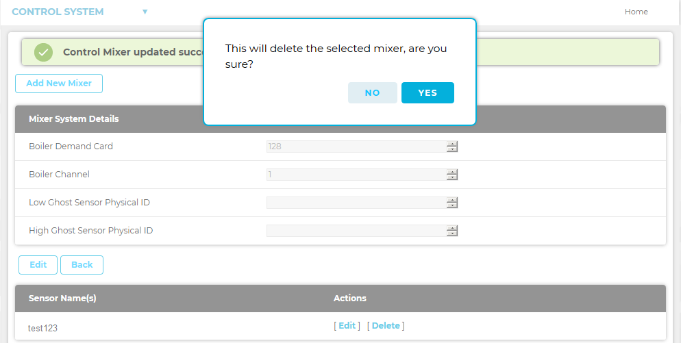
To Delete a Control Mixer Sensor
1.In the Actions column of the Sensor Name(s) section of the Mixer Settings [Control Device Group name] window , click on [Delete] in the row containing the Sensor to be deleted. See Figure 1394 above.
2.Click on Yes in the displayed warning window. See Figure 1395 below:
Figure 1395
•The selected Control Mixer Sensor is deleted.