Contents
EMS allows the User to allocate Plans to a Zone. Plan View gives a graphical view of the data.
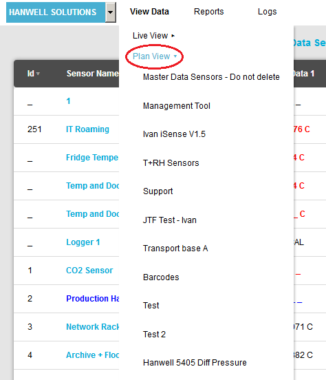
1.From the required Site's Live View window, select Plan View in the View Data menu to expand a list of available Zones. See Figure 1074 below:
Figure 1074
2.Click on the required Zone in the expanded list
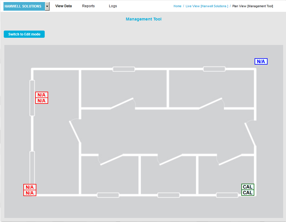
•The Plan View [Zone name] window is displayed for the selected Zone with a default background plan. See Figure 1075 below:
Figure 1075
To Upload an Alternative plan to the displayed Default plan:
| Note: | You must have Plan View Edit Permission set to Allowed to be able to do this. |
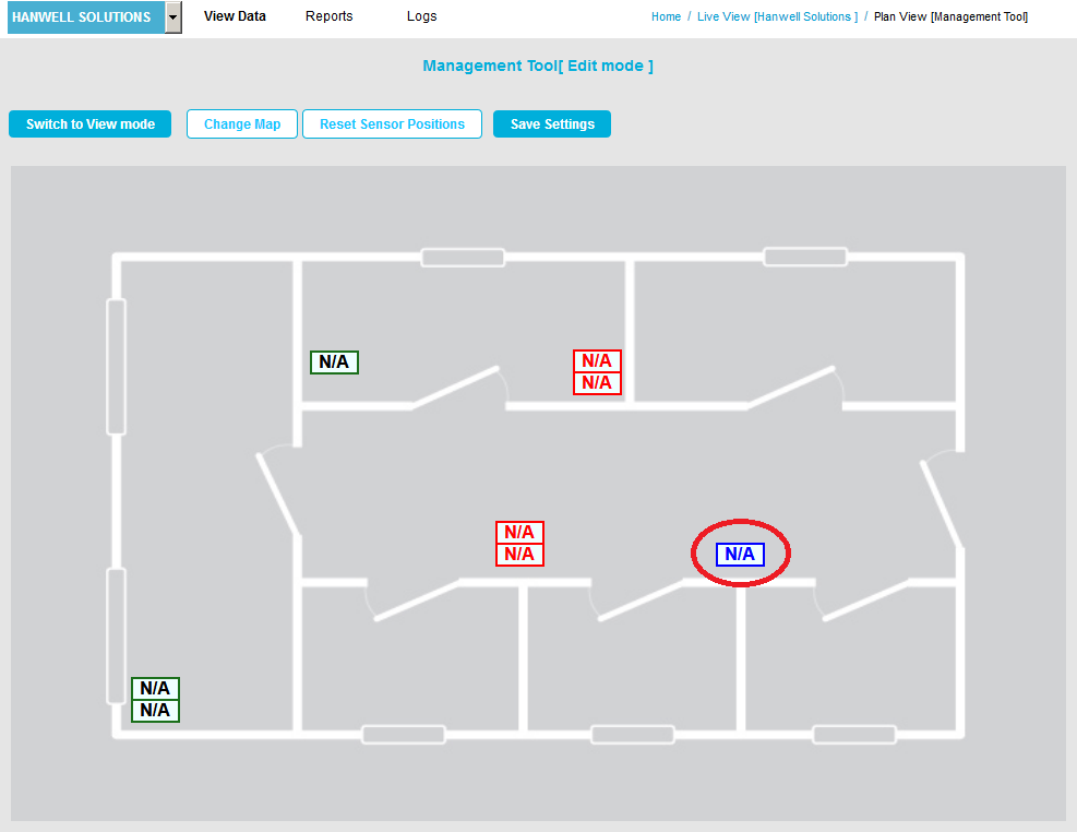
1.Click on the Switch to Edit Mode button to display the following window. See Figure 1076 below:
Figure 1076
2.Click on the Change Map button.
•The Change Background window is displayed. See Figure 1077 below:
Figure 1077
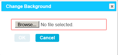
3.Click on the Browse... button, navigate to the required plan's location in the displayed File Upload window and highlight it.
| Note: | Suitable Plan formats are .gif, .jpg and .png. Plan file size should be no larger than 100Kb. |
4.Click on Open in the File Upload window.
•The file's name is displayed in the Plan View window, next to the Browse... button. See Figure 1078 below:
Figure 1078
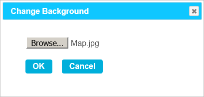
5.Click on the OK button on the Change Background window.
•The new Map/Background is displayed.
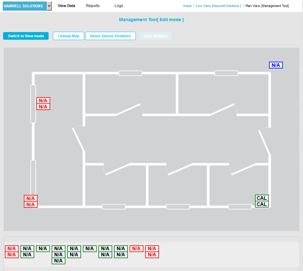
•When a new plan is first loaded, all of the Sensor icons will be located along the bottom bar. See Figure 1079 below:
Figure 1079
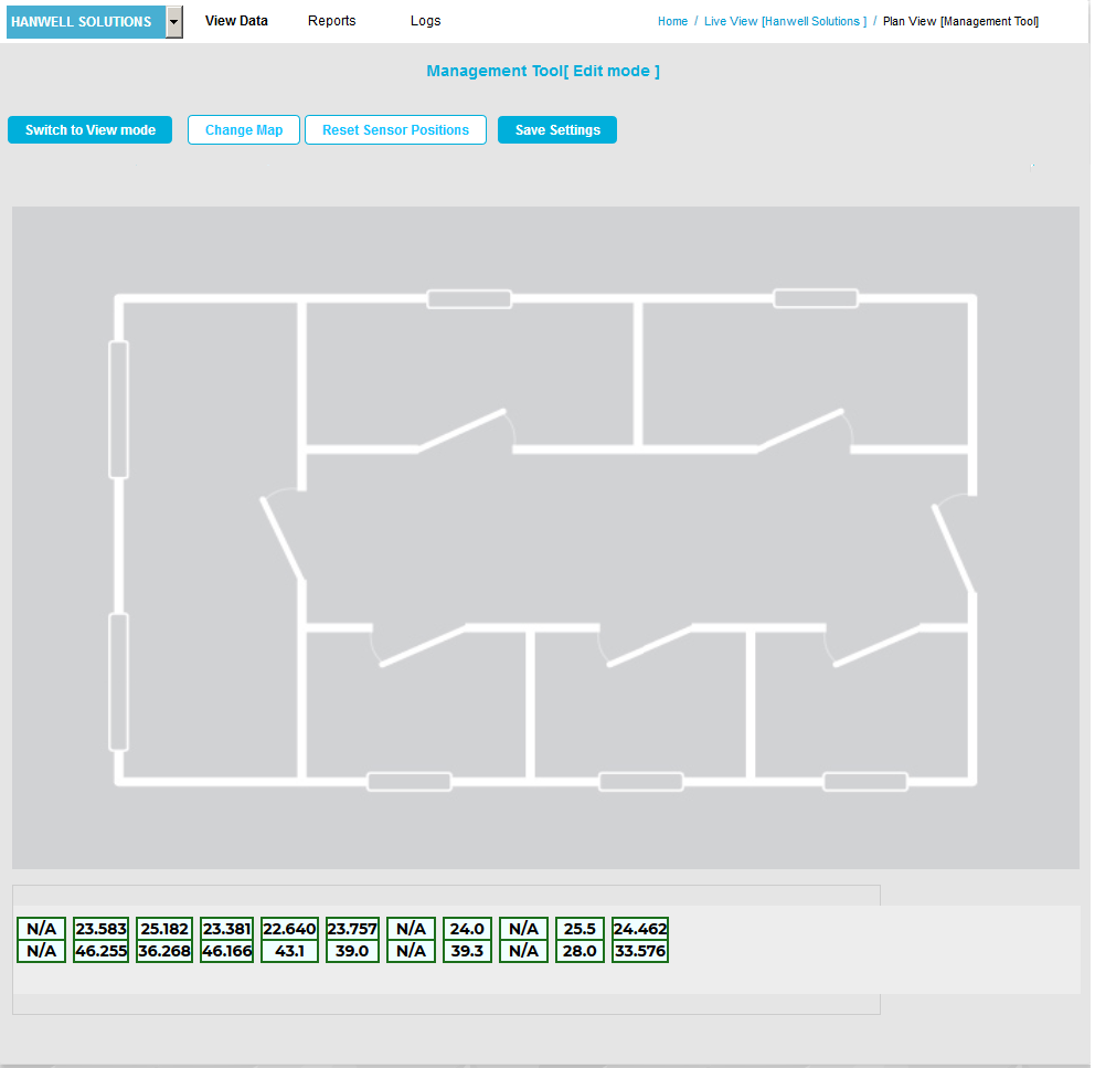
•The icons can be dragged onto the Plan by moving the mouse cursor over the icon, holding down the left mouse key and dragging the required Sensor icon to the desired location on the Plan.
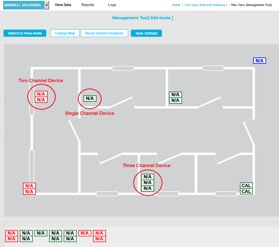
•Clicking on the slider to the right of the bottom bar (if displayed) scrolls the list of available Sensors up and down, showing any further available Sensor icons. See Figure 1080 below.
Each channel is represented by a single icon block:
•A single-channel device is represented by a single icon block.
•A double-channel device is represented by two icon blocks.
•A three-channel device by three icon blocks.
See Figure 1080 below for examples:
Figure 1080
If required all icons can be removed from the Plan and returned to the bottom bar as follows:
1.Click the Reset Sensor Positions button: ![]()
•A Warning dialog is displayed. See Figure 1081 below:
Figure 1081
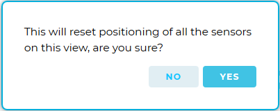
2. Click Yes to reset all Sensors' positions; all icons will be moved to the bottom bar.
• To cancel the reset, click No.
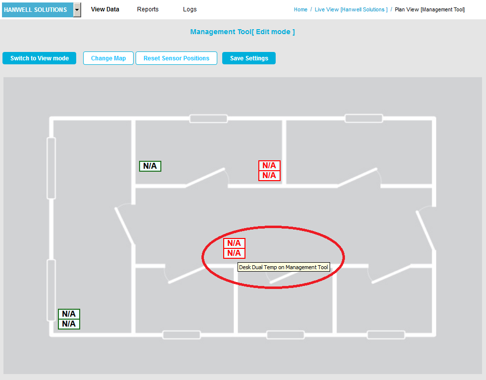
Moving the mouse pointer over a Sensor's icon block displays a tool tip showing the Sensor's name and its parent Zone. See Figure 1082.
Figure 1082
•‘Out of Service’ Sensors are displayed on the Plan View in dark blue. See Figure 1083.
Figure 1083