Navigation:
System Configuration Sensors > Configuring Sensors > Calibration - General >> Calibration - Using the Remote Management Tools
Calibration - Using the Remote Management Tools

Contents
Calibration involves checking the values recorded by a Sensor against values known to be correct (the Reference Values) and confirming that the two are equal.
See: Calibration Glossary of Terms
If necessary, a Sensor's Calibration Settings are then adjusted to ensure that it's displayed and transmitted values accurately correspond to these Reference Values.
•Other terms for Reference Values are Applied Values or Calibration Points.
Sensors can be calibrated on-site by the Client or Hanwell personnel by using the following procedure.
| Note: | This procedure assumes that the EMS Remote Management Tools have been installed and that suitable calibration equipment (for example a Humidity Generator or Dry Block Temperature Generator) is available. |
Using the EMS Remote Management Tools for Calibration
As well as EMS, Calibration requires the use of the EMS Remote Management Tools.
Opening the EMS Remote Management Tools
1.Open the EMS Remote Management Tools by -
Either:
Clicking on the Desktop Icon:

Or:
Selecting it's entry in the Start menu.
•The EMS Connection window is displayed. See Figure 840 below:
Figure 840
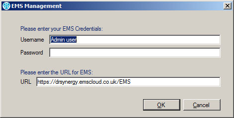
2.Enter a Username and Password and the URL of the EMS System that you wish to communicate with.
•The URL will be in the form: http://<hostname>/EMS/, replace <hostname> with the Hostname or IP address used to reach your EMS server.
3.Ensure that the fields' entries are correct and click OK to continue.
Selecting the Sensors to Calibrate
The EMS Management window is displayed once the Remote Management Tools have loaded. See Figure 841 below:
Figure 841
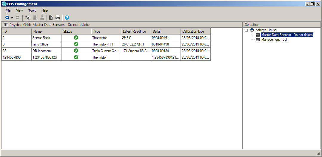
•Sensors can be browsed to by navigating Sites and Groups.
To switch the view mode between Sites and Groups,
Either:
Select the corresponding View menu option.
Or:
Click on the appropriate Tool Bar button.
•Sites and groups can be navigated by; using the tree view to the right of the screen, using the Next Grid and Last Grid options in the View menu or using the Back and Forward tool buttons in the top left of the screen. See Figure 841 above.
•Sensors are selected by simply clicking on their icons.
The Synchronise process takes data from a connected USB device and updates its Serial Number and Calibration details in EMS at the same time as setting the Physical Transmit ID of the device.
•Synchronising Sensors facilitates efficient communication between the Sensor and EMS.
•Even if the Sensor is already running on EMS, it is strongly recommended to carry out Synchronisation to set a faster transmit rate for the Calibration run.
To Synchronise a Sensor:
1.Ensure that the Sensor is connected via a USB cable.
2.Select the correct Sensor using the EMS Remote Management Tools. See Figure 841 above.
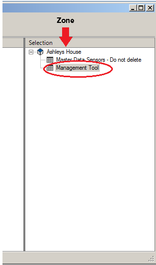
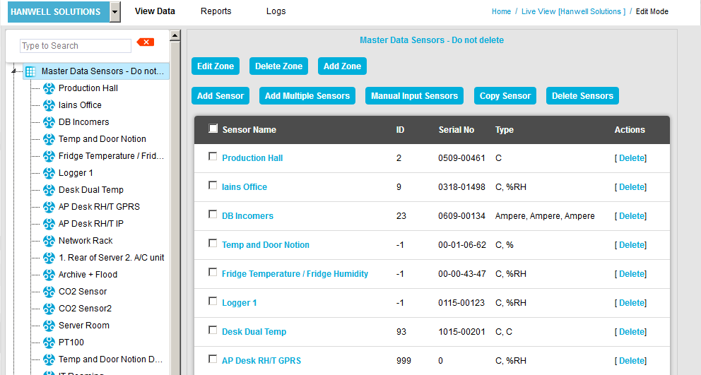
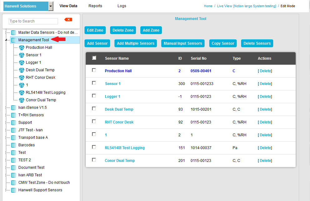
3. Click on the correct Zone in the right-hand Selection field of the EMS Management window. See Figure 842 below.
4.Select Management Tool from the Zone’s expanded entry. See Figure 842 below:
Figure 842
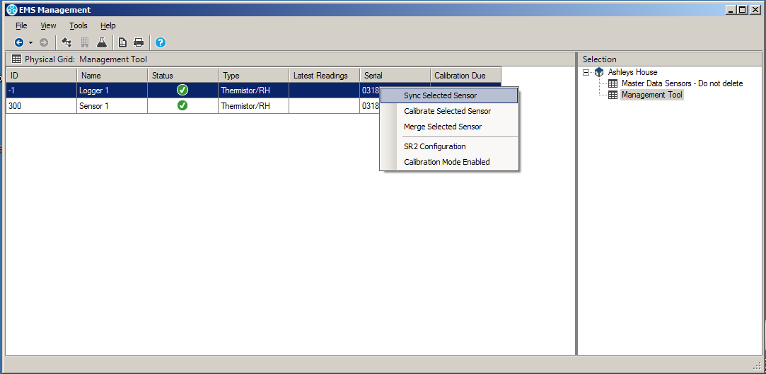
5.Right click on the selected Sensor and select Sync Selected Sensor from the displayed drop-down menu. See Figure 843 below:
Figure 843
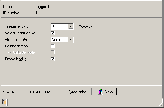
•The EMS Synchronise USB Sensor Vx.x window is displayed. See Figure 844 below:
Figure 844
| Note: | The Sensor selected must match the physical device or the program will not complete. |
6.Make a note of the value in the Transmit interval field, so that the Unit can be reset after calibration.
7.Select the required TX interval from the Transmit interval drop-down list (60 seconds is recommended for Calibration).
•The EMS Synchronise USB Sensor Vx.x window completes loading and all the fields are populated.
8.Click the Synchronise button and follow the instructions given until it reports that the Synchronisation is complete.
9.Close the window to finish and update the EMS database.
10.Repeat this procedure for all Sensors.
Selecting Reference Values
•The chosen Reference Values should be equally spaced within the published temperature range of the Sensor/Transmitter, but can take account of the actual range of temperatures that the particular Sensor/Transmitter will be subject to.
•A minimum of three Reference Values should be chosen to calibrate a Sensor - High, Medium and Low within the required value range.
•It is not advisable to calibrate over a very small range. For example, if a Unit was being used at in an environment at +5°C and had calibration points of, say, 0, +5 and +10°C applied, if the Unit was then moved to an environment at +30°C the calibration would be invalid.
However, if the Unit was always going to be used in an environment with a temperature range between 0°C and +10°C and readings outside this range were unimportant, then it would be fine to calibrate over the narrower range.
Recording Reference Values
1.Set up the Sensors/Transmitters to be calibrated and an appropriate Reference Probe in suitable calibration equipment (for example a Humidity Generator or Dry Block Temperature Generator).
2.Set the calibration equipment to the required Reference Value and leave it to stabilise i.e. give a consistent reading at this value.
•As this value is set by the Client/Hanwell it can also be known as the Applied Value.
3.Make a note of the reading from the Reference Probe and the time it was taken.
•This is the Reference Value i.e. the value which the Sensor should record and will be adjusted to match if not.
Recording As Found Calibration Data
1.Double click on the entry for the Sensor being calibrated in EMS.
2.Zoom in on the graph to get a reading from the same time the Reference Value's reading was taken.
•This reading will be your As Found reading ie. the value that the Sensor 'sees' at, for example, the actual temperature/humidity represented by the Reference Value generated by the calibration equipment and measured by the Reference Probe.
3.Make a note of the As Found reading.
Recording Raw Calibration Data
1.Check the Reference Value's reading again. This should not have drifted.
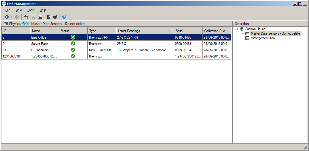
2.Using the EMS Management Tool, check the that the latest readings (listed in the Latest Readings column of the EMS Management window) for the Sensor being calibrated are the same as the As Found readings displayed in EMS noted above. See Figure 845 below:
Figure 845
3.Select a Sensor or Sensors, then put the Management Tool into CAL mode (View > Calibration Mode).
•The entries in the Latest Readings column will be highlighted in pink and their Raw Numbers displayed. See Figure 846 below:
Figure 846
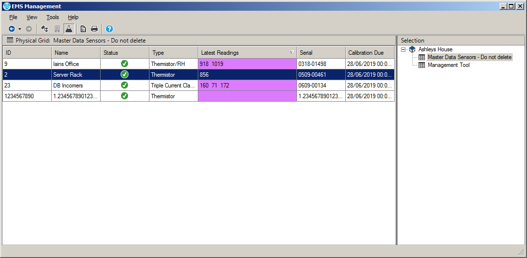
4.Note down the Raw Numbers generated by the Sensor from the Latest Readings column.
•These represent the Raw Numbers generated by the Sensor at the selected Reference Value.
| Note: | For Dual Sensors, two Raw Number values [ 1 ]-[ 2 ] will be given; Temperature being represented by Channel 1. and Humidity by Channel 2. Not all Sensors/Transmitters have two channels, some have one and others have three and will display one or three Raw Numbers respectively. |
5.Repeat steps:
•Recording Reference Values
•Recording As Found Calibration Data
and
•Recording Raw Calibration Data
for the remaining selected Reference Values.
If the As Found values are the same as the Reference Values, the Sensor is accurately measuring the actual values and no adjustments are required. In this case, go to Resetting TX Interval below.
If the As Found values are not the same as the Reference Values, you will need to adjust the Sensor's Calibration Settings. See Editing a Sensor's Calibration Settings below:
Editing a Sensor's Calibration Settings
To edit a Sensor's Calibration Settings, possibly following an event such as an annual re-calibration.
In EMS:
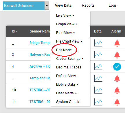
1.From the required Site's Live View window, select Edit Mode from the main View Data menu. See Figure 847 below:
Figure 847
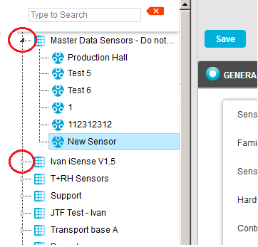
2.In the left-hand menu of the displayed Editing and Configuration window, click on the + symbol next to the Zone containing the Sensors to be accessed. •The selected branch will expand showing all of the available sensors for the selected Zone. See Figure 848 below: Figure 848
3.Click on the + symbol next to the Sensor name to view the properties of the Sensor that is to be Edited. •This will expand the branch again to show the Properties folder for the Sensor. See Figure 849 below: Figure 849
4.Click on the + symbol next to Properties to access the individual Sensor properties. •This will expand the branch again to show the Sensor's configurable Properties. See Figure 850 below: Figure 850
5.Click on the + sign next to the Calibration icon to expand the Calibration property entries. See Figure 851 below: Figure 851
6.Click on the icon(s) representing the parameter(s) the Sensor is measuring, in this example the Temperature or Humidity icon, to display the parameter's window, in this case, the Temperature or Humidity window, for the selected Sensor/Transmitter. See Figure 852 and Figure 853 below: Figure 852
Figure 853
7.Enter the selected High, Mid and Low Reference Values into the High Calibration:, Mid Calibration: and Low Calibration: Fields. 8.Enter the Raw Numbers from the As Found readings into the High Raw:, Mid Raw: and Low Raw: field for the corresponding High, Mid and Low Reference Values. •This will 'tell' EMS that these Raw Numbers represent the specific Reference Value rather than the incorrect values originally generated by the Sensor from the Raw Numbers. 9.Select Update to confirm the details and apply the Calibration adjustment. •If the Update has been successful, the following message will be displayed. Figure 855 below: Figure 854
10.Repeat for all Sensors. Note: For large numbers of sensors it may save time if you take advantage of the Export Calibration Data functionality to avoid navigating through the above procedure to access each sensor's properties. |


•The Site's Edit Mode window is displayed. See Figure 855 below:
Figure 855
•By default, the Sensor and Zone editing/configuration window for the Zone at the top of the left-hand menu is displayed.
•To display another Zone's Edit Mode window, click on the entry for the required Zone in the left-hand menu. For an example, see Figure 856 below:
Figure 856
2.Either:
i.In the left-hand list of the Zone's Edit Mode window, click on the small 'arrow' symbol to display a list of the Sensors associated with the Zone. See Figure 857 below:
Figure 857
ii.In the left-hand list, click on the required Sensor's icon ![]() .
.
Or:
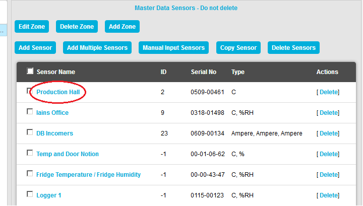
In table in the Zone's Edit Mode window, click on the required Sensor's name in the Sensor Name column. See Figure 858 below:
Figure 858
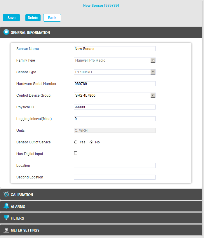
•The Edit Mode window for the selected Sensor is displayed. See Figure 859 below:
Figure 859
3.Click the on the Calibration field to expand the Calibration pane. See Figure 860 below:
Figure 860
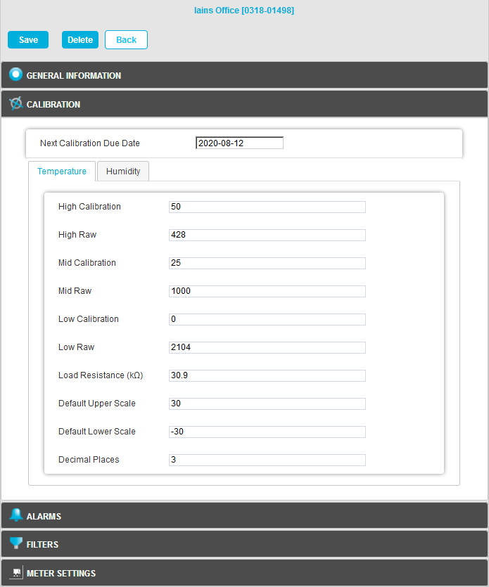
4.Click on the tab(s) representing the parameter(s) the Sensor is measuring, in this example the Temperature or Humidity tab, to display the selected parameter's window for the selected Sensor/Transmitter. See Figures 861 below:
Figure 861
|
|
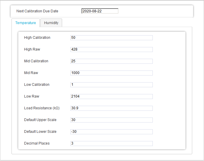
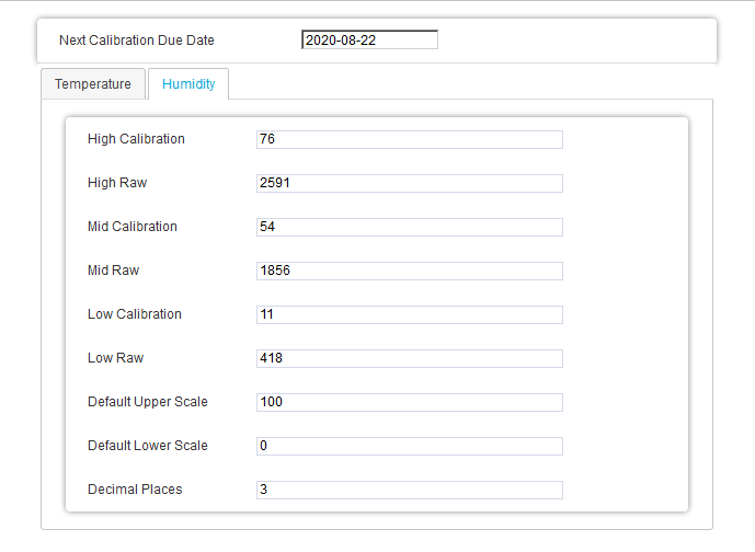
5.In the selected parameter's window, enter the selected High, Mid and Low Reference Values into the High Calibration:, Mid Calibration: and Low Calibration: Fields.
6.Enter the Raw Numbers from the As Found readings into the High Raw:, Mid Raw: and Low Raw: field for the corresponding High, Mid and Low Reference Values.
•This will 'tell' EMS that these Raw Numbers represent the specific Reference Value rather than the incorrect values originally generated by the Sensor from the Raw Numbers.
7.Click on the Save button (see Figure 860 above) to confirm the details and apply the Calibration adjustment.
•Click on the Back button to cancel any changes to the Calibration due date.
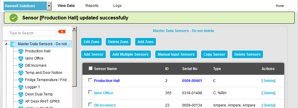
•If the Update has been successful, you will be returned to the Zone's Edit Mode window and the following message will be displayed. See 862 below:
Figure 862
8.Repeat for all Sensors.
| Note: | For large numbers of Sensors it may save time if you take advantage of the Export Calibration Data functionality to avoid navigating through the above procedure to access each Sensor's properties. |
Sending Calibration Values to Units
This Calibration process takes Sensor Calibration settings, either existing or recently adjusted, from the EMS database and loads them into a selected Sensor.
•Additionally, during the Calibration Process, the High High and Low Low Alarm Settings are also loaded into the Sensor.
To send Calibration values to a Sensor:
1.Ensure that the Sensor is plugged in using a USB cable.
2.Select the Sensor from the EMS Remote Management Tools EMS Management window and right-click on its entry in the table.
3.Select Calibrate Selected Sensor from the displayed menu.
•The EMS USB Sensor Calibration Vx.x window is displayed and its fields are populated. See 863 below:
Figure 863
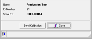
| Note: | The Sensor's Serial Number and Type must match or the program will not complete. |
4.Click on the Send Calibration button and follow the instructions given until it reports that the calibration is complete.
5.The Sensor's display should show the same value as displayed in EMS.
6.Repeat steps 1 - 5 for all Units.
Recording 'As Left' Calibration Data
Before completing the Calibration, check Sensor As Left readings at all Reference Values.
•The readings should be close to the Reference Values taking into account the margins of error of the equipment/process being used.
•Note down the As Left readings on the worksheet.
•The readings shown on the Sensor's display and in EMS should match if the above process has been carried out correctly.
Resetting TX Interval
1.Using the Synchronise process in the EMS Remote Management Tool, reset the TX interval for each Unit to its original interval recorded earlier.
2.Repeat for all Units.
Calibration Certificate
If a Calibration Certificate is required, use the use the data above to fill out its details ie:
High, Low and Medium Raw Numbers/Counts
High, Low and Medium Reference Values
High, Low and Medium As Found Values
Export Calibration Data for Selected Sensors
This Remote Management Tool functionality enables the export of Sensor Calibration Data/Parameters for a large number of Sensors from EMS to an Excel spreadsheet from where their calibration parameter values can be quickly edited.
•This avoids having to navigate to each individual Sensor's properties, as outlined in Editing a Sensor's Calibration Settings above, to change their calibration parameter values.
The edited calibration parameter values can then be imported back into EMS.
| Note: | This functionality only works with Hanwell Pro Sensors. |
Exporting Calibration Data/Parameters
1.Select Export Calibration Data from the Data menu bar entry in the EMS Management window. See 864 below:
Figure 864
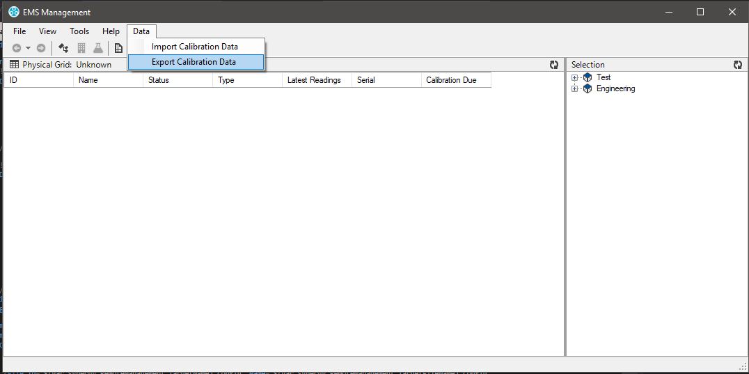
•The Export Calibration Data window is displayed, showing a tree view containing the Sensors available to export Calibration Data from. See 865 below.
| Note: | Which Sensors are displayed in the tree view depends on which view the Customer was in prior to selecting Export Calibration Data from the Data entry in the main menu bar. For Example: If the customer was in Logical Groups before navigating to the Export Calibration Data screen, Logical Groups will be shown in the Export Calibration Data screen. See 865 below: |
Figure 865
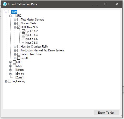
2.Tick the relevant Sensor's check boxes to select them.
3.Click on the Export To Xlsx button.
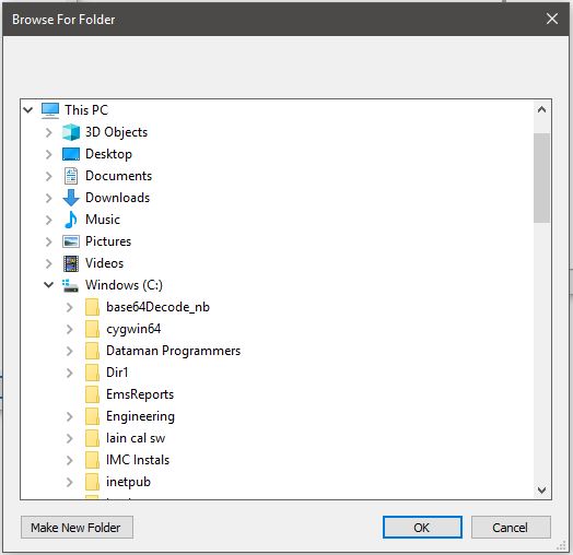
4.Either:
Select an existing location for the generated .xlsx file in the displayed Browse for Folder window. See 866 below.
Or:
Click on the Make New Folder button in the displayed Browse for Folder window to create a new folder for the generated .xlsx file and define its location. See 866 below:
Figure 866
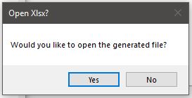
•When the .xlsx file has been generated, the following window will be displayed, giving you the option of opening the file. See 867 below:
Figure 867
•Clicking on Yes, or opening the file at a later date, displays the calibration data/parameters for the selected Sensors in the format displayed in 868 below:
Figure 868
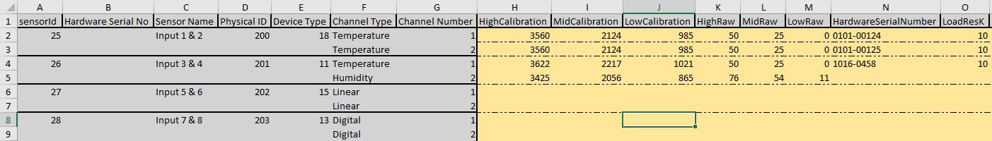
•Once the data/parameters have been exported, the customer can modify their values in the .xlsx spread sheet and then import them into EMS to update the existing data/parameter values.
| Caution: | The Excel spreadsheet and the data/parameters in it will not be checked on the import, so extreme caution should be exercised when making changes with this method. |
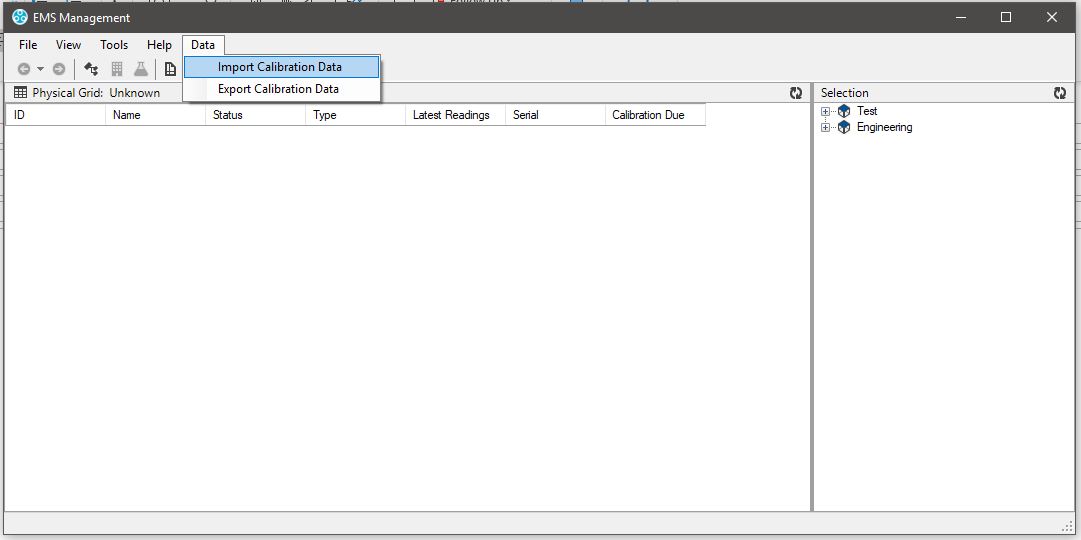
Importing Edited Calibration Data/Parameters
Select Import Calibration Data from the Data menu bar entry in the EMS Management window. See 869 below:
Figure 869
| Note: | On import, an entry in the Audit Trail will be made to say who carried out the change, when the changes were made, what the old data/parameter values were and what the new data/parameter values are. |
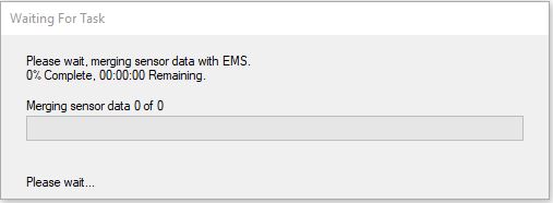
•The Waiting For Task window is displayed as the new data/parameter values are imported into EMS, updating the database. See 870 below:
Figure 870