Navigation:
Installation, Configuration and Operation of Hardware > Installation and Configuration of Additional Devices > ARB Module > ARB Module Operation >> Relay/Buzzer and MS100 Card Operation
Relay/Buzzer and MS1000 Card Operation

Contents
Relay and Buzzer Operation
EMS can be configured to trigger the ARB Module's internal relays and buzzer, if specified Sensors go into alarm, as follows:
1.Create a Sensor Group in EMS.
Note: A Sensor Group is only visible to the User who created it and cannot be shared with or made visible to other Users.
2.Add the required Sensors to the Group.
3.Assign the required Local Alarms to the Sensor Group.
4.Select the Relay Output in the associated Local Alarms.
When an alarm in the associated Sensor Group occurs, the ARB Module's relays will switch contacts; the Normally Open relay closes, the Normally Closed relay opens.
•The buzzer sounds when either relay switches contacts.
Cancel Relays
Relay operation for the current alarm(s) can be canceled by pressing the Cancel Relay Operation button adjacent to the power connector; this will cancel the relays operation until a new alarm occurs.
Silence Buzzer
Pressing the Mute key will silence the buzzer until a new alarm occurs.
MS1000 Card Operation
EMS can be configured to switch outputs on MS1000 cards connected to the ARB Module's RS485 Bus, if specified Sensors go into alarm, as follows:
1.Create a Sensor Group in EMS.
Note: A Sensor Group is only visible to the User who created it and cannot be shared with or made visible to other Users.
2.Add the required Sensors to the Sensor group.
3.Assign the required Local Alarms to the Sensor Group.
4.Select the required MS1000 Channel Number for the Relay output.
When an alarm in the associated Sensor Group occurs, the MS1000 Relay output will switch; this can be used to drive a sound alarm, beacon or auto-dialer.
Connecting the MS1000 Card
The MS1000 Control Unit receives control signals from the ARB Module via Hanwell and Customer supplied, RS485 twisted-pair cables.
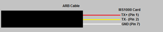
ARB Connections to MS1000 card
•Red cable: To MS1000 Card Pin 1 (TX+)
•Yellow cable: To MS1000 Card Pin 2 (TX-)
•White cable: To MS1000 Card Pin 7 (GND)
Powering the MS1000 Card
•The ARB Unit would does not provide the 12V voltage required to power the MS1000 cards; MS1000 cards need to be powered externally from a 12V PSU.
➢The MS1000 Control Unit is powered from a single phase 240V 50Hz local mains supply from a switched feed, fused at 3 Amps. This generates +12V to power the MS1000 Output Cards and Control Board (if applicable).
oThe internal 0V reference is connected to local PE (Protective Earth).
oWiring supplying power to the Control Unit should be rated above 13A.
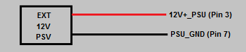
External PSU Connections to MS1000 Card
•External PSU 12V+: To MS1000 Card Pin 3 (+12V)
•External PSU GND: To MS1000 Card Pin 7 (GND)
Refer to Document GD6063: MS1000 Control System Installation Guide for more information.