Click here to go to Online Help for the EMS Mobile App
●EMS - Description
●EMS - Functionality
●EMS - Main Concepts and Architecture
●EMS - Management and Monitoring of 3rd Party Control Equipment
●EMS - Remote Management Tools
●EMS - User Names and Passwords
●EMS Compliant
EMS - Description
●EMS Provides a Browser Based Graphical User Interface (GUI) for Hanwell Wireless Monitoring Installations.
EMS employs a browser based GUI (Graphical User Interface) which is totally separate from the underlying hardware and allows Users to connect to EMS from any commercially available browser, such as Explorer or Firefox, and access data via an Intranet or, optionally, over the Internet.
| Note: | The Host machine and Client machines MUST have one of the following browsers installed: |
➢Internet Explorer 10 or 11. ➢Microsoft Edge (Windows 10) Version 42 or later. ➢Google Chrome Version 72 or later. ➢Mozilla Firefox Version 65 or later. Support for Browsers is unlikely to end, especially given the numerous companies involved in their creation, maintenance and development. Therefore the risk of problems caused by Operating System Providers ceasing product support or even going out of business is minimised.
| Note: | Although other browsers generally work with EMS, they are not guaranteed to be fully compatible; earlier versions of Internet Explorer do not support all EMS features. |
|
●EMS uses an SQL database making it easy to quickly and efficiently manage and access large amounts of data.
➢SQL databases use well defined standards, which are being adopted by ANSI & ISO, enabling an SQL database to be used by 3rd-party tools if required/commercially desirable. ➢EMS is shipped in two variants to allow for differing locations and installations of the SQL database: W900A and W900B: W900A or W900B Installation?
EMS can be provided as an A or a B: W900A and W900B respectively
Which one is appropriate needs to be decided before installing EMS as each requires different pre-requisites to be in place.
●An A install puts the SQL database on the same Target Server (i.e. where data is sent to from the Control Devices) as the EMS software. If the Target Server does NOT have an existing Microsoft SQL Server instance and you do not wish to use and/or have an appropriate Microsoft SQL Server available on the LAN, then EMS W900A/W906A is required.
➢W900A is distributed with an SQL 2022 Express (with tools) Bootstrapper, which will install SQL and Microsoft SQL Server Management Studio on the EMS Server. ➢During W900A installation, the System Administrator password is set to: P3nd13H0us3. This is done solely to provide a password without User interaction; EMS does not use the System Administrator account. ●A B install puts the SQL database on another machine/server from the Target Server (i.e. where data is sent to from the Control Devices). If there is an existing Microsoft SQL Server on the Target Server or LAN that you wish to use for EMS, then EMS W900B/W906B is required.
➢W900B is distributed without SQL and is intended for installation where the customer wishes to use an existing SQL instance. | Note: | EMS ONLY supports versions of Microsoft SQL from 2014 onwards. |
|
➢Existing Microsoft SQL Instance
If there is an existing Microsoft SQL Server on the target Server or LAN that you wish to use for EMS, then the following conditions must be met:
❖EMS W900B must be used. ❖The existing Microsoft SQL Server must be a version from 2014 onwards. ❖SQL Instance must be set to SQL login and Windows Authentication mode. ❖The installing Windows login should be a member of the sys admin Role and must have full Administrative Privileges for the SQL Instance. ❖SQL Server Browser Service must be running during EMS install and EMS Config Utility operation. ❖SQL Server Management Studio (SSMS) must be installed. |
➢Restoring an SQL Database
Restoring an SQL database requires all other connections to the database to be closed. If doing this from SSMS or similar, run the MS Services MMC (Microsoft Management Console) and make sure that Apache and all of the EMS Services are stopped first; also, close any open SSMS edit windows connected to the database being restored.
|
|
●EMS is Scaleable
EMS is a Scalable Application which can be installed on a single site with one User, up to hundreds of Sites with thousands of Users, allowing seamless support for both large numbers of Sensor communication protocols and very large numbers of Sensors, over multiple sites.
|
●EMS offers a wide range of User options and configurations, ensuring future proofing and ready customisation to the User's particular circumstances.
●Given the necessary permissions, EMS allows the User to rapidly change options and configuration details.
●EMS gives you control of Exception Handling Protocols; the various options do not have to be generically configured by the Administrator.
●EMS is a Services-Based System.
●The EMS architecture ensures that support for as yet unknown hardware can be readily integrated (future proofing) by modularising the hardware services and accessing the database via a universal interface module.
EMS - Functionality
EMS has two key strands of functionality:
●Extensive Reporting and Logging capabilities with custom reports available as easily accessible plug-ins to the main System and the capability to transmit Alerts.
●The ability to act as an interface between Hanwell wireless monitoring equipment and 3rd party control equipment such as Motorised Valves and Alarm Sounders.
EMS - Main Concepts and Architecture
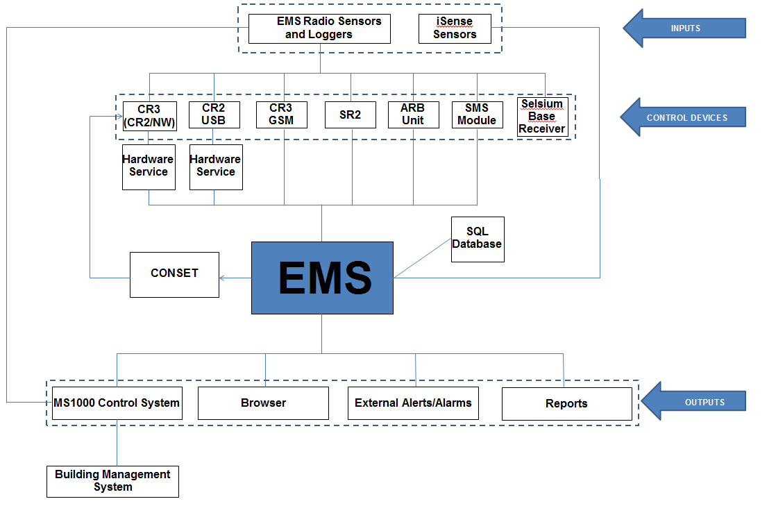
Figure 6
Overall Structure of EMS
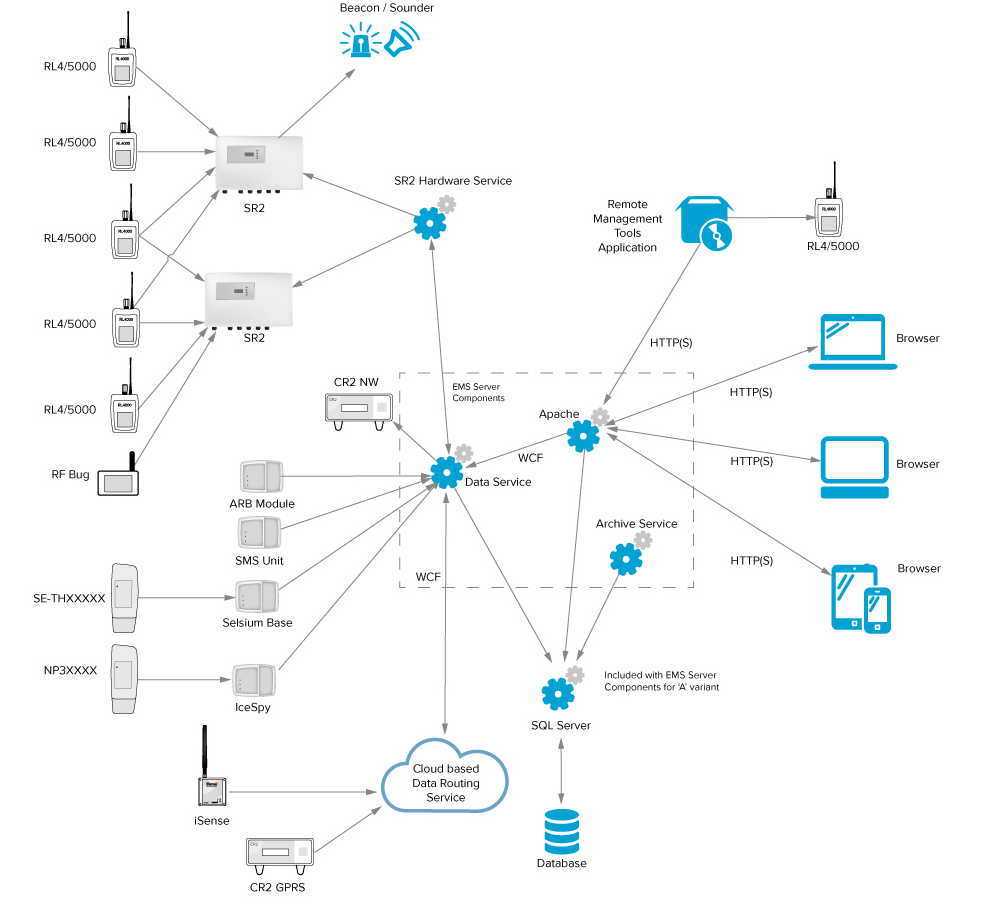
Figure 7
EMS System Diagram Showing Possible Configurations
EMS - Inputs
EMS - Data Input and Handling
●Hanwell Radio Sensors and Loggers
➢Data input into EMS is mainly generated by wireless Hanwell Sensors and Loggers which collect data/readings at the Site. ➢EMS works with the Hanwell 12bit RL, ML and HL ranges of Radio Sensor Transmitters and Loggers. Note: EMS is not compatible with legacy 8 and 10 bit devices.
iSense Sensors
➢iSense Sensors can be used to remotely collect and transfer Sensor readings to the EMS System via the cellular telephone network. ➢iSense Sensors are handled as a special Sensor in EMS; they are not part of a Control Device Group and have a special PID value of zero. EMS collects iSense data by making an outgoing TCP/IP connection to the Hanwell Remote Data Service. As this connection is made to the standard HTTP Port – 8081 on the Hanwell Remote Data Service, the System operates, in the vast majority of cases, with no need to make network or Firewall configuration changes.
|
●Control Devices
Control Devices relay data acquired by the Sensors and Loggers to the EMS Server by either TCP/IP (Internet or Intranet), USB connector and cable or GPRS (mobile/cellular phone network).
The collected data is then stored in EMS's associated SQL Database and made available for viewing via a Local Management Application or a standard Web Browser.
There are several types of Control Device (more maybe added in the future):
➢SR2
The SR2 is a network connected Control Device that collects data from radio Sensors; it has a supplementary power supply to enable the collection and retention of data during a mains power outage.
➢SR2s can also drive outputs – such as sounders and beacons – when an alarm condition occurs. ➢EMS will work with legacy SR2 Control Devices. The SR2 Hanwell Smart Receiver/Controller is a network enabled receiver, designed for continuously monitoring environmental data from multiple points within a site, or across multiple sites, receiving and processing data signals from Hanwell radio and wired Sensors. Additionally, the SR2 can be fitted with up to eight onboard probes and can be upgraded to a transceiver to both receive and re-transmit the data.
➢Each SR2 can handle data from up to 254 Sensors and, as up to 16 SR2s can be run on a single System, up to 4048 Sensors can be connected to a single System. ➢The SR2 logs all received data in its on-board 512kb memory. ➢The software continually interrogates the SR2 for the most recent data. It then downloads the data according to User-defined Logging Periods to the Server or operating PC, from where Software Users can view live and historic data, produce Reports and set Alarms for both data values and the rate of change of the data’s values. ➢An optional remote Receiver can be connected to improve radio reception in difficult areas. ➢Alarm relays are included; these can indicate that the readings are out of specification and can, optionally, be set to indicate a network failure. ➢An MS BUS connection allows the SR2 to drive the Hanwell MS1000 Control System. ❖Hardware Service SR2 Control Devices
SR2 Control Device types connect to EMS via their own Windows Service, known as a Hardware Service; other Control Devices, apart from CR2 USB Control Devices, are connected directly to/from the EMS Data Service.
➢The SR2 Hardware Service can be local or remote to/from the EMS Server. ➢The SR2 Hardware Service can handle connections to multiple SR2s. |
|
➢CR3
CR3 Controllers receive and processes data signals from Hanwell radio and wired Sensors and are designed for continuous monitoring of an entire System.
•Received data is then logged and stored, pending transfer to a PC for analysis and archival storage. •The CR3 also signals alarm conditions via the front panel LEDs (should any Sensor measure above or below individual pre-set levels). •Although the CR3 Controller has an extensive memory capacity, it is intended that the data is transferred to a PC for detailed interpretation and permanent storage. This can be done, automatically or manually, at any time. •A built in GPRS modem for remote communications is also available. ➢CR2 USB
Customers converting from RadioLog can use their legacy CR2 USB Control Devices to continue collecting Sensor data.
Hardware Service CR2 USB Control Devices
CR2 USB Control Device types connect to EMS via their own Windows Service, known as a Hardware Service; other Control Devices, apart from SR2 Control Devices, are connected directly to/from the EMS Data Service.
•The CR2 USB Hardware Service can be local or remote to the EMS Server. •CR2 USB Hardware Services can handle connections to multiple Control Devices, which may themselves be distributed remotely. •Each CR2 USB Control Device connected to an EMS System requires a separate PC with the CR2USB Service installed. |
|
➢CR3 (CR3 NW)
CR3 (CR3 NW) network connected Control Devices can be used to collect radio Sensor data and can also drive outputs – such as Sounders and Beacons – when an alarm condition occurs.
•CR3 (CR3 NW) Control Devices can also be used for Conservation Heating Control, driving both digital and analogue outputs, using a range of radio and RS485 connected cards. Please contact your Distributor or Hanwell Sales, for specific requirements. •Control Settings Functionality
This EMS functionality allows the configuration of Hanwell CR3 (CR3 NW) Control Devices' outputs to external 3rd party control Systems via a Hanwell MS1000 Control System.
Conset is used only for configuring the Control Settings. Once configured the CR3 (CR3 NW) is autonomous requiring no external software or network connection to operate.
|
|
➢CR3 GSM
CR3 GPRS (CR3 GPRS)
CR3 GPRS Control Devices can be used to remotely collect radio Sensor data and then transfer the collected data to the EMS System using the cellular telephone network.
|
|
|
●Other Control Devices
➢ARB Unit
The ARB module (Hanwell Part Number: IN-NA002) is an optional piece of IP53 rated hardware that works with the EMS System and provides users with additional functionality, such as visual and audio alarms, RFID for data backfill and a Bluetooth interface for interacting with handheld devices, not available with other devices.
|
➢SMS Module
The SMS Module gives the ability for Transmitter alarms to be sent as SMS messages to mobile phones. See SMS Global Settings, SMS System Alerts, User Alerts, and SMS Heartbeat, for details of SMS configuration. Key features:
|
➢TME7000
The TME HM007 ThermoBarScan is a hand held temperature recording device with a Sensor probe, integral barcode scanner and Bluetooth capabilities.
|
➢Hanwell IceSpy Module
The IceSpy Calibration Module collects data from the Hanwell Solutions Calibration Tool (part of the EMS software) and transfers the data to transmitters via RFID.
|
➢Hanwell Pro Repeater Module
Hanwell Pro Repeater Units receive signals from radiotelemetry Sensors and re-transmit the signals on to CRx Controllers and SRx series Smart Receivers, effectively increasing their radio range.
|
➢Hanwell IceSpy Repeater Module
The Hanwell IceSpy Repeater (previously known as the IceSpy Echo) Module provides a Repeater function for transmitted signals, should this be required in your installation.
|
➢Hanwell IceSpy Sensor-Transmitters
All the members of the Hanwell IceSpy Transmitter family have the same basic enclosure (see above) and share many common characteristics.
The available Sensor-Transmitters can monitor:
•Temperature and Relative Humidity (RH), using either internal Sensors or Sensor probes attached to the Sensor-Transmitter Unit. •Voltage inputs (1V, 5V and 10V) and Current inputs (4-20mA), enabling the use of external third party Sensors with Linear Sensor-Transmitters. An example of such an application is the Hanwell IceSpy CO2 Sensor Assembly - IN-CO2-10 (10%) and IN-CO2-5 (5%).
•The Sensor/Transmitters can also provide door alarms. •There are also external PT100 and thermocouple Sensor probe options. For more detail on the Hanwell IceSpy Transmitter family, see: https://hanwell.com/shop/hanwell-icespy/hanwell-icespy-temperature-Sensors/
|
➢Selsium Base Receiver
Selsium is an add-on product for EMS, designed primarily to monitor and record temperatures in fridges used to store drugs on hospital wards.
Additional Selsium features include the printing of Alarm Alert messages to ward printers; a Selsium Base Alarm buzzer; the ability to Acknowledge Alarms from the Base and Selsium Reports.
|
|
Sites, Zones and Groups
EMS introduces the concepts of Sites, Zones and Groups
●Sites
➢The allocation of Sites enables the collection of data from distributed Systems and locations and allows the connection of multiple distributed data collection devices to an EMS installation. ➢Sites are the main access points to the System Data. ➢Each Site represents a single physical location where receiving Control Devices such as SR2 Smart Receivers, CR2 or CR3 Controllers are sited, along with measuring Sensors and their associated Transmitters. ➢An EMS System can encompass numerous distributed Sites. | Note: | More than two Sites will require additional licencing. |
➢Sites can have Sub-Sites; there is no functional difference between a Site and a Sub-Site. ➢Different Sites can be on different time zones; where this is the case, displayed Sensor data will reflect the local time for the site. |
●Zones
A Site's Sensors can be grouped together into Zones.
Zones are used to logically group Sensors.
➢Though such a logical grouping can relate to a Sensor or Sensors physical location within a Site, it can also relate to any other factor common to a collection of Sensors. ❖For example, a Zone could be called First Floor Sensors and contain Sensors of different types but all located on the first floor or could be called RH-T Sensors and contain all of the Humidity and Temperature Sensors.
Note:
|
Zones replace the Grid System previously used in RadioLog.
|
|
●Groups
EMS allows you to select any combination(s) of Users, Sensors or Control Devices to form Groups, i.e. sub-sets of the group of all Users/Sensors/Control Devices in an EMS System, with all subsequent operations (alarms, reporting etc.) only operating on that Group/sub-set.
➢User Groups
User Groups allow Viewing Privileges to be set for a group of Users, rather than individually for each User.
•Privileges are the viewing rights that allow an individual User or User Group to see Sites and Zones. •By assigning and denying Privileges, a User or User Group can be restricted in the number of Sites and Zones they can see. This is especially useful on very large Systems. •Users added to a User Group inherit the viewing Privileges associated with that User Group. Note: Any previous viewing Privileges assigned to an individual User will be overridden by the viewing Privileges associated with the group the User has been added to.
|
➢Sensor Groups
EMS has the capability to group Sensors of the same type together into Sensor Groups.
•Sensors in a Sensor Group can be located on different Sites. | For example: | For a series of rooms where temperature and humidity are being measured, the Sensors measuring these parameters can be brought together into one group. |
•Once grouped, the Sensor Group can be set to show an average value for all of the Sensors in that group. Sensor Groups are also used to control SR2 Alarm Relays, CR3 Alarm Relays, ARB Alarm Relays/Buzzers and associated MS1000 Control Interface outputs via the Local Alarms settings.
|
➢Control Device Groups
•A Control Device Group is a named collection of one or more Control Devices and associated Sensors. •A Control Device Group defines the polling interval for Control Devices in the Group. •CR2 and CR3 Control Devices each have their own Control Device Group; whereas multiple SR2s can be used in a single group. •Within a Control Device Group, all Sensors and Control Devices must operate on the same frequency. ➢This will only apply to multiple SR2s as single CR2 and CR3 Control Devices, and their associated Sensors, in their own Control Device Group (see above) will only operate on a single frequency.
i.e: Groups of Sensors and SR2s on the same frequency can be in one or more Control Device Groups; but a single Control Device Group must not contain SR2s and Sensors on more than one frequency. ➢Physical Identifier (PID)
All Sensors associated with a Control Device Group must have a unique PID in the range 1 to 254; e.g. there can only be 254 Sensors in a Control Device Group (see iSense Sensors however).
Where a System uses multiple Sensor frequencies, Sensor PIDs can be duplicated/shared between different frequencies, but the Sensors on each frequency will need to be allocated to separate Control Device Groups.
|
|
|
EMS - Outputs
Sensor Data Viewing and Reporting
●Viewing Sensor Data
●Reporting Sensor Data
EMS has been designed to be able to accommodate Custom Plug-in Reports of information generated from, and related to, the System's Sensor/Transmitters.
➢The Reports can be tailored to the Customer’s individual specifications and generated at the click of an on-screen button in PDF format, with the option to have a .CSV data file attached. ❖Additionally, User Configurable Scheduled Reports can be generated and, once configured, be auto-generated on a daily, weekly or monthly basis and sent to the User by email. ➢Scheduled Reports can be downloaded and saved in PDF format. ➢Your Company Logo can be automatically added to any standard (PDF or RTF) report. Four types of Report are available:
➢Summary Reports ➢Calibration Reports ➢Exception Reports ➢Scheduled Reports |
●User Alerts
User Alerts provide automated Alert notifications; delivered via Email, SMS or both.
| Note: | Additional hardware is required for SMS Alarms. |
➢Email Alerts
The EMS System enables the use of Password Authenticated Accounts to login to SMTP & POP3 / IMAP servers. EMS can also be set to use SSL / TLS to secure email server connections.
The email account password is stored as encrypted data, using a machine specific key; as such, moving EMS data from one machine to another will break the key and the password will need to be reset using the Email Alert Global Settings screen in a browser.
If required, assuming a suitable POP3 or IMAP email server is available, the EMS System can be configured to enable the use of email replies to acknowledge Alarm alerts.
EMS’s Email Alert Groups System is very flexible, allowing multiple groups to be set up with different Sensors, alarm types and active days or times for sending SMS alerts to various recipients. Different recipients can be set to receive SMS for different alarm types on the same Sensor and/or for alarms occurring at different times of the day.
Alerts can also be emailed for various System events (see below).
|
➢SMS Alerts
When used with an SMS Module, EMS can send SMS alerts in response to Sensor alarms, various System events (see below) and power or network communications failure.
EMS’s SMS Alert Groups feature is very flexible, allowing multiple groups to have different Sensors, alarm types and active days or times, for sending SMS alerts to various recipients, to be defined.
➢Different recipients can be set to receive SMS for different alarm types on the same Sensor and/or for alarms occurring at different times of the day. | Note: | Additional hardware is required for SMS Alarms. |
|
➢Email/SMS System Alerts
System Alerts can be sent (via Email or SMS) in response to:
➢System Start up (includes previous System Shutdown information); ➢Login Fail; ➢System Edit; ➢Hardware Events (e.g. an SR2 going offline). ➢System Stop Alert EMS is a web-based product, with a number of backend services, running on a server; a User closing the programme cannot shut it down.
However, there are three possible shutdown scenarios:
❖Software failure; ❖Administrator action; ❖Power failure. In order to facilitate fast shutdown, reducing the risk of consequential data loss, following one of the above three scenarios, the Data Service detects and writes details of a shutdown to an XML file.
This file is then used to generate an Activity Log entry, which the Data Service will then send as part of a System Start Up SMS / Email Alert when the System is next started.
|
|
EMS - Management and Monitoring of 3rd Party Control Equipment
The Hanwell MS1000 Control System provides an interface between EMS and 3rd party control equipment and alarm sounders.
EMS - Remote Management Tools
The EMS Remote Management Tools are a collection of applications that enable direct Communication Setup and Configuration tasks that cannot be performed from a browser.
●EMS Remote Management Tools are a collection of applications that enable EMS Administrators direct access to the EMS Server to perform Communication setup and Configuration tasks on the EMS Server that cannot be performed from a browser.
●Using these Tools, Communication setup and Configuration tasks on the EMS Server can be performed on computers on the LAN, local to the EMS Server, or on computers that are remote from the EMS Server.
For example, EMS Remote Management Tools would enable EMS Administrators to synchronise Sensors and setup SR2s on computers that are remote to the EMS server.
| Note: | EMS Remote Management Tools require http (Port 80) or https – where EMS System is configured for https - connection to the EMS server. |
EMS - User Names and Passwords
Because EMS’s Primary User Interface is browser based, allowing Users to connect from any browser on the local network and, potentially, from remote locations as well, all Users must login with a User Name and Password.
EMS Passwords are case sensitive, EMS User Names are not.
| Note: | '@' and '-' symbols are allowed in User Names. |
EMS Compliant
EMS Compliant incorporates features which meet the security requirements of FDA 21CFR Part 11.
•FDA 21CFR Part 11 is an FDA (US Food and Drug Administration) regulation regarding the security of electronic data records; including the electronic signature on a record.
EMS Software (W906A and W906B) can be supplied with an FDA 21CFR Part11 licencelicense(W901) that activates the features required for Compliance with FDA 21CFR Part11, thereby ensuring that the electronic records - either in the form of the data records or in the form of the event log / audit trail - cannot be altered and any attempted tampering will be flagged.
When Counter Signatures are enabled in EMS Compliant, there will be a facility to enable any User to act as a Countersigner or Approver for actions, carried out by the System Administrators, which lead to System-wide or significant configuration changes.
•For details on applying the W901 licence,licensesee EMS Software Licencing - Counter Signatures (W901 Only).
See also:
•Hanwell EMS Compliant User Manual. Document Number: IM6148
•EMS FDA 21 CFR Part11 & Validation User Guide. Document Number: SV6155
| Note: | When installing 21CFR Part 11 Compliant software the correct Hardware and Software Installation Qualification (IQ) and Software Operational Qualification (OQ) workbooks must be completed at the time of installation.
When upgrading any 21 CFR Part 11 Compliant software the correct Software upgrade IQ and OQ workbooks must be completed at the time of installation. |
Differences between EMS Compliant and EMS Standard.
Confirming Activities - Minor Changes
Activities which alter System Operation or affect data recording and result in Audit Trail entries in the Activity Log, require confirmation.
These activities include:
•Acknowledging Alarms.
•Setting Alarm Levels.
•Changing User Alerts.
•Changing Scheduled Reports.
When such changes are submitted by the User, the Login control window will be displayed. See Figure 8 below:
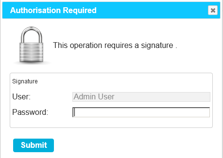
Figure 8
•The User is required to enter their password into the Password field and click Submit to confirm the changes.
Confirming Activities - System Changes
Activities which lead to system wide or significant configuration changes also require Counter Signatory confirmation.
These activities include:
•User Management.
•User Group Management.
•Device Configuration.
•System Configuration.
•Editing Sites.
•Changes to Access Control.
When such changes are submitted by the User, the Counter Signatory control will display. See Figure 9 below:
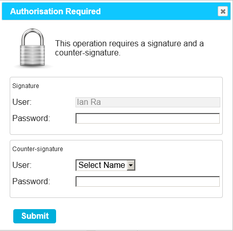
Figure 9
This requires the currently logged in User to enter their password into the Password field.
In addition, a User who has Counter Signature Access Control permission must then:
1.Select their User Name from the User Name (Counter Signatory) dropdown list.
2.Enter their password in the Password (Counter Signature) field.
3.Click Submit to confirm.
•See Figure 9 above.
Turning off Counter Signatures
As stated above, with Compliant EMS installed and a W901 Licencelicenseapplied to it, you will have Counter Signatures applied to your system and turned on by default.
•You have the ability to turn off the Counter Signatures using the EMSConfig utility. See EMS Software Licencing - Counter Signatures (W901 Only).
Scheduled Reports
Some EMS Reports include additional information to assist with CFR21 compliance and have a Signature version, which includes Signature and Comment boxes to aid with CFR21 compliance.
